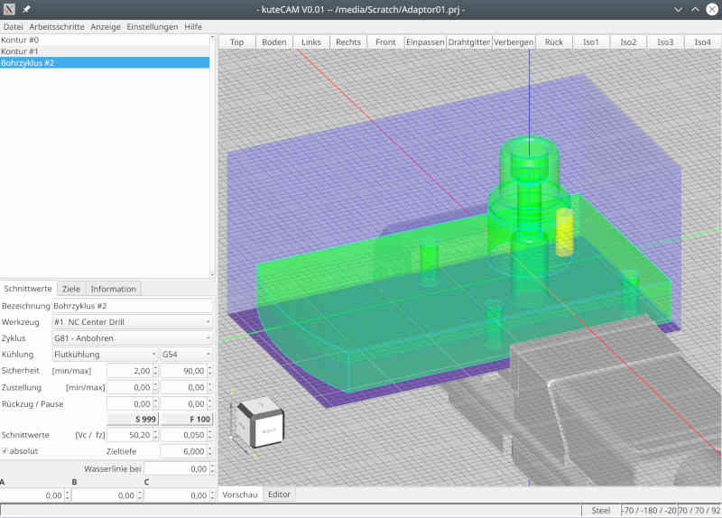
simple linux cam
- Reinhard
- Offline
- Platinum Member
-

- Posts: 508
- Thank you received: 94
I just added motion preview of toolpaths with speed control:
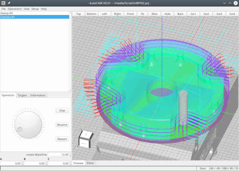
Tool shape is created based on informations from tooltable.
Attachments:
Please Log in or Create an account to join the conversation.
- silopolis
- Offline
- Junior Member
-

- Posts: 23
- Thank you received: 4
Sorry for the delay man, missed notification :/
Thank you for your attention and your flowers
Keep in mind, that I'm at the very beginning of a huge project ...
")
You're very welcome, and I'm both very conscious and aware of the job at hand, so let me renew my support !
Do you have an option to machine "by area" instead of "by depth" ? Could avoid a bunch of rapid moves,
Don't know what you mean with "by area" and don't know neither whether I got you right.
Well, this is a lingo I got from another CAM package for an option that is reordering path fragments into "towers" instead of layers, if I can explain it like that.
Maybe with this it will be clearer:
Path fragments piled up in each rectangle are machined one after the other with decreasing Z height until final Z depth is reached. Then machining moves to another "area" or "pile", and again same fragments of decreasing height are processed.
Instead of having all fragments at the same Z height machined, with transitions between fragments (which may have to avoid obstacles), and return to "layer" start point (obstacles again ?), this is frequently an interesting optimization both in terms of machining time because total path length is shorter as you spend less time in transition rapids, as well as safety as having moves confined in areas diminish risks by reducing transition rapid moves to the minimum.
When part shape and generated path allows, being able to add a "stay down" option to this can lead to huge air cutting time savings
I plan the application in such a way that the user selects some elements from the model and I, or rather kuteCAM, then knows what to do.
Next best things after automatic features recognition, but let's keep that for v0.2

In no case I plan to reinvent a CAD.
Yes, please lol
Even though I am at the very beginning, I'm already very satisfied with my progress (I have very little sparetime) and so far I have been able to implement everything as planned. Therefore, I am confident and continue to follow my plans.
Excellent, strong and steady !
"Stay down" is an (important) option for finishing. So far, I am dealing exclusively with roughing and stay down is not important for roughing.
See my comment above. I'm actually using it quite often, with adaptive strategies too.
Currently, I am still working on implementing general purpose processing. So far from any optimization. To visualize the way my processing works, take this picture:
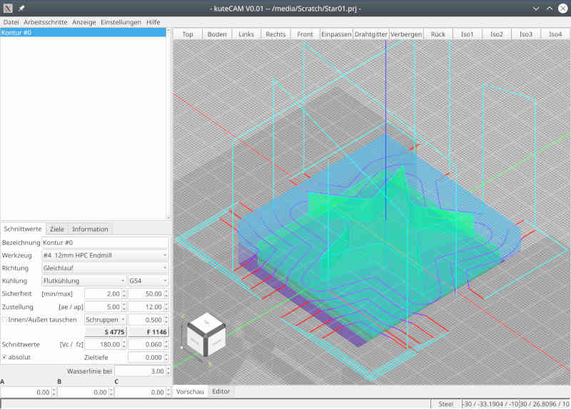
The dark blue lines are the "real workpath" where the tool should cut material. The red lines are "lead-in" and "lead-out" to ensure, that the tool is completely outside of the model.
Path fragments colorization is, IMHO, as helpful and thus important as syntax highlighting in the code editor !
May I suggest a different color for leads in and and leads out ? In some cases like small holes, it can get tricky to easily and clearly distinguish them.
I cut the virtual working area into smaller areas and as long as the tool stays in one area, the tool will stay down.
For area changes, I move up to save retraction layer. That's a place for later optimization, but actually I don't waste a thought on it.
The "by area" option would then be to machine everything in that area down to final depth before leaving it with retraction to safe height.
Looking back, I have to confess, that I lost most dev-time in debugging and understanding randomly/unpredictably results from occ and creating a reliable layer between occ and my app. Apparently occ has no interest supporting hobby users, so I have to fight my battle alone (not my preferred way of working)
So I'm not sure how much effort I'll still putting into occ. I have the impression by using occ it always goes one step forward and yet two steps back - or to put it another way: occ is the most expensive foreign library I have ever looked into. Even though I think I've understood quite a bit, I'm sure I've only lightly scratched the surface.
Every time this lib is mentioned, it is to express pain and suffering :/
I'm wondering what CAMotics uses ?!
Keep up the great work
TY
J
Attachments:
Please Log in or Create an account to join the conversation.
- silopolis
- Offline
- Junior Member
-
- Posts: 23
- Thank you received: 4
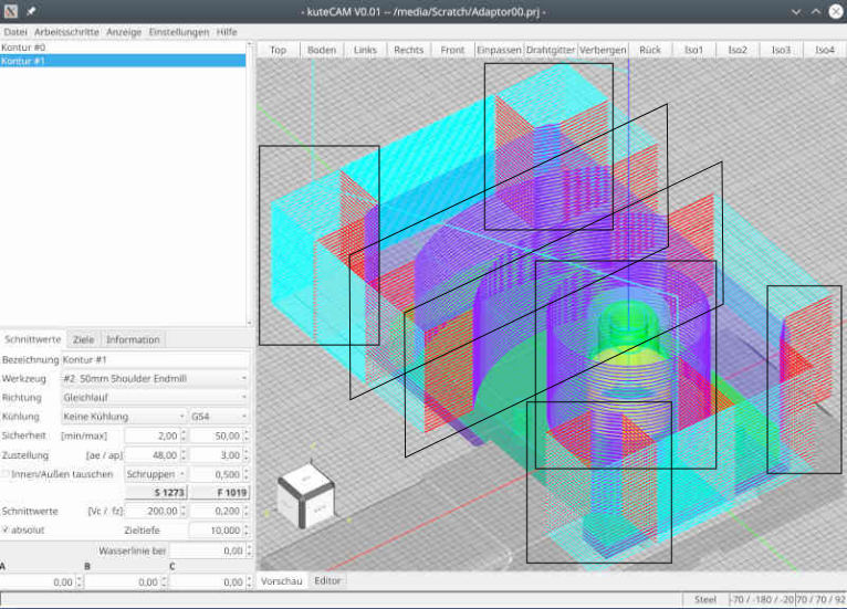
This is perfect for a broad range of cases, if not most of them. Like said in previous message, this can become from less than optimal on larger parts with distant machined areas and eventually problematic when there can be obstacles in the way... Which in turn makes me think a "force retract" (between each cutting fragment) option could be a life saver in some cases !I took a closer look at cylinder job and how to optimize it. Regarding "stay low" - all movements for one z-height are already performed as "stay low", which means, changing Z happens only, when a new Z-height will be milled.
An alternate (shorter?) path might look like this (the green line) - from top view: [...]
but I fear, that with this path, the cylinder is not round but something like the blue line. So I need a full turn around the cylinder anyway. Drawback of the green path - it works only as long as the workpiece is smaller that double the diameter of the tool.
Not fond of it neither.
Maybe "areas" are more easily seen from top:
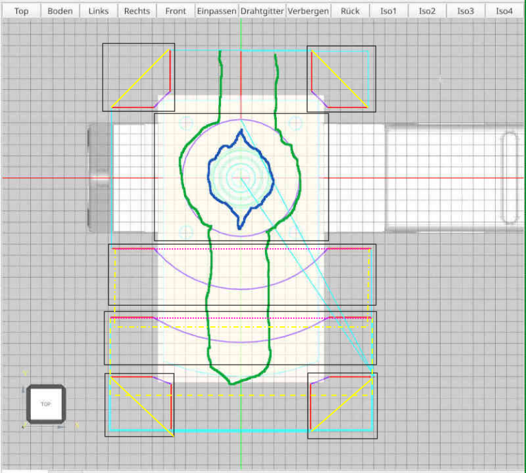
Also:
- yellow plain lines can be "stayed" down rapids
- yellow dashed and point dashed could be "stayed" down rapids with an optional small clearance retract like in adaptive path
- pink dotted lines could be shortest path safe height retracted rapids
Like I said originally, I very much like it and next best thing would be an adaptive path !My actual variant works for any shape and any dimension of the face below the cylinder.
My "by area" and "stay down" suggestions was only potential optimizations that I believe could be beneficial for some kind of parts.
I believe "both direction" strategy always delivers the shortest path as you don't have to go find the next suitable lead in and just reach the nearest as fast as possibleSo I think, a really shorter workpath could be created, if you don't care for cutting direction (alternating parallel feed and against feed).
TY
J
Attachments:
Please Log in or Create an account to join the conversation.
- Reinhard
- Offline
- Platinum Member
-
- Posts: 508
- Thank you received: 94
thank you for your attention!
Tower processing is an interesting option, but I believe, its not always the best way.

I think, it works good for the 4 corners, but does not work for towers 3 and 4 ...
This is the workpiece:
so on processing towers 3 and 4 you have to lift the tool or move around the workpiece.
So I guess, I stay at the moment with current path creation and keep the tower processing in mind for later optimization.
Path processing with alternating cut direction will lead to completely different toolpath.
> I believe "both direction" strategy always delivers the shortest path as you don't have to go find the next suitable lead in and
> just reach the nearest as fast as possible
Sure! But the shortest toolpath is not the best respect to tool lifetime. Some machines don't support "parallel feed" and "against feed" might kill the milling tool earlier. So I think, user should decide, what to generate ...
> I'm actually using it quite often, with adaptive strategies too.
I read about adaptive path generation quite often, but I don't know, what it means. I can only think of, how I would code the path on my machine. In certain situation I already generate paths, which I would never code manually, but because its too much work coding it manually.
So may be I could improve path generation when I know, what adaptive intends to provide ...
> Path fragments colorization is, IMHO, as helpful and thus important as syntax highlighting in the code editor !
> May I suggest a different color for leads in and and leads out ?
Path colorization is far from final. Actually I change colors by the needs on working at path generation.
My final path actually just distinguishes between fast move and moves with work feed. I thought about attaching a color to certain tool, so that it is easier to distinguish.
... but I'm open to suggestions.
Looking at the star - the red lines are leadin/leadout.
Working at the open pockets from the round chuck adapter I used different colors for start and end of the path - just to be sure, that it goes in the right direction ...
... but I removed the coloring on publishing the feature
> Also:
- yellow plain lines can be "stayed" down rapids
- yellow dashed and point dashed could be "stayed" down rapids with an optional small clearance retract like in adaptive path
- pink dotted lines could be shortest path safe height retracted rapids
Yellow plain lines won't work "down rapid". Lead out is about 0.6D, so yellow plain lines crashes the part.
Yellow dashed lines of cause need a retract of tool
Pink dotted - yes, could move in safe height.
Guess I have to create a sample to calculate whether it really saves fast moves
")
Thank you for your valuable input!
Attachments:
Please Log in or Create an account to join the conversation.