QT C++ code samples
- Grotius
-
 Topic Author
- Offline
- Platinum Member
-

Less
More
- Posts: 2419
- Thank you received: 2345
13 Jun 2019 15:34 - 17 Jun 2019 00:00 #136834
by Grotius
Replied by Grotius on topic QT C++ code samples
@John Thornton,
That is very good news.
I hope our road's will cross once in software development and deployment.
That linuxcnc will have once a free code C++ cad / cam package is clear.
A cad cam coded top level language is a must to stay as free as a bird.
Ubuntu with linuxcnc, why not? Or is this GPL3? The GLP institute is fooling everybody....
Student's can hack into the provided code samples, below.
They can write their own code to it to get their bachelor's degree in computer science, and the KISGLP2 (keep it simple gpl2) argument is one of the basic's to make progress.
My project can take over 1 to 5 year's. But i have time and like other users over here, we never give up hope.
The provided code QT C++ samples are including at the moment :
1. Use external variables over different file's. (QT project file attachments in previous posts)
2. Draw a line with QT openGL. (QT project file attachments in previous posts)
Number 3 will be a new item, i did not try this item in C++ before, but it has to do with how to keep Cad Cam program's simple and structured.
A perfect way for student's to set up the Cad / Cam program top level logic structure.
It is a combination of Parametric Cad user input and Dxf input displayed into the Screen (openGL) and conversed to (ngc) G-code output.
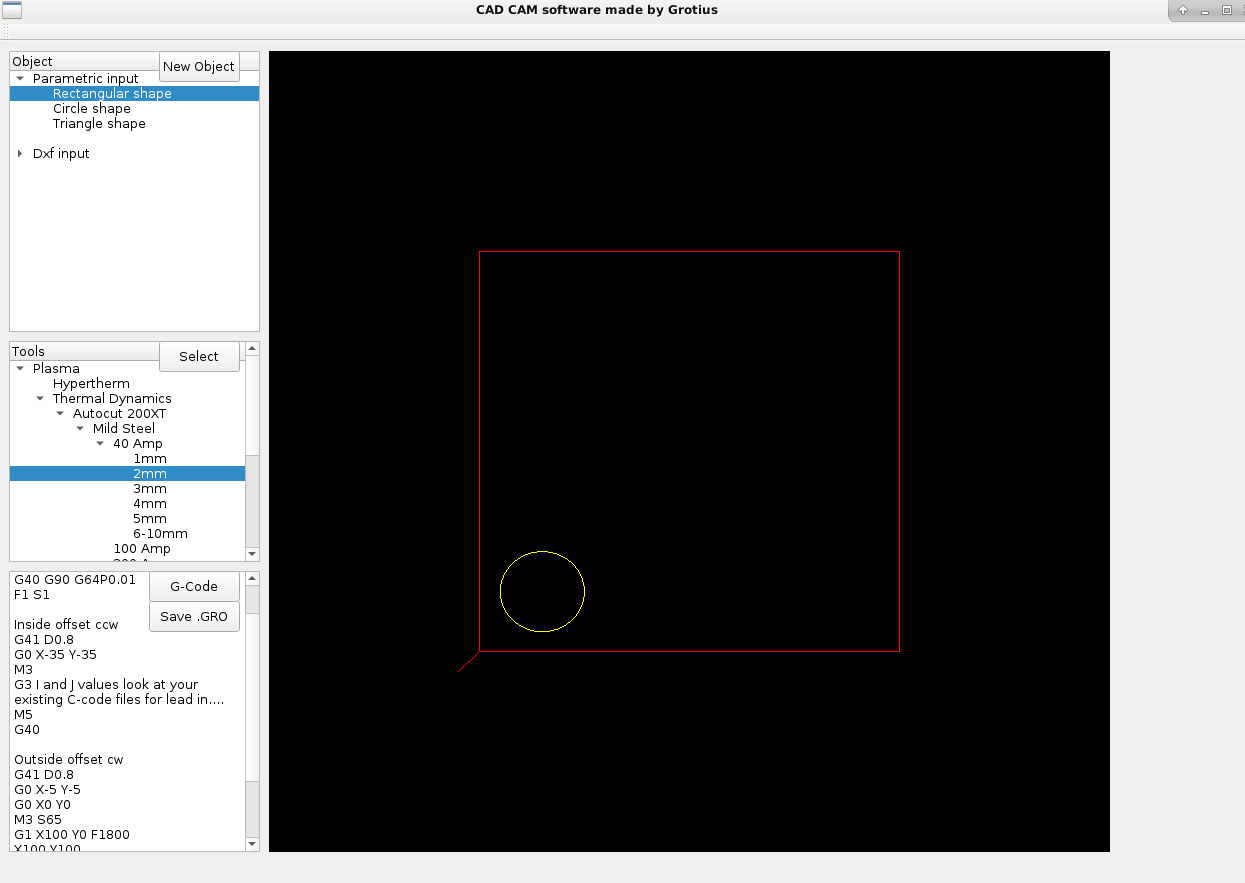
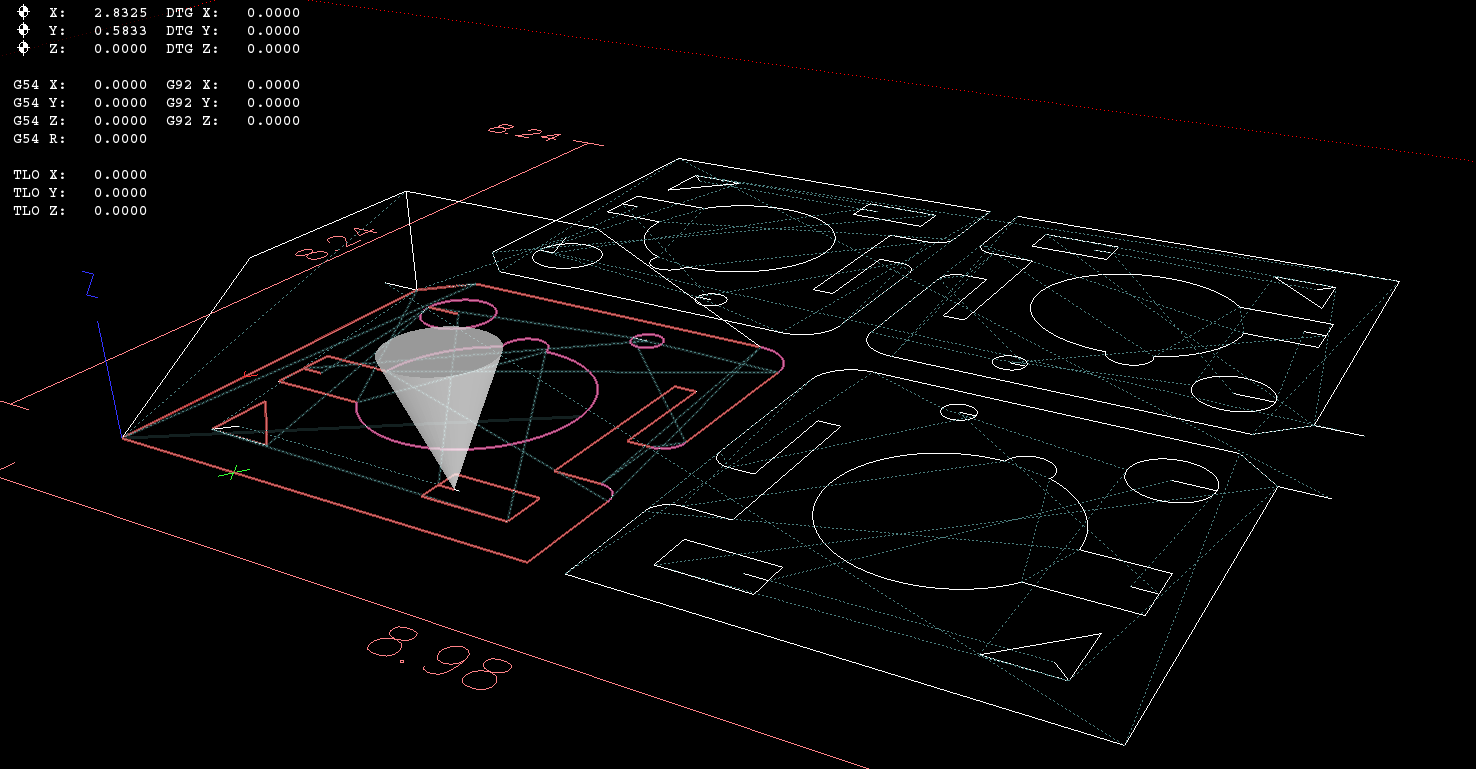
It can select cut chart's, see picture. I am waiting for official factory approval to include the TD factory parameters and HP parameters.
So i hope to include a bare C++ example soon of how to implement this logic into the program structure.
It will be saved as a .GRO file.
This output structure i have to design. It includes a brand new logic.
It include's the logic for dxf, ngc, tools, and so on in one file.... But this .GRO file output will be better structured then Autodesk has ever done over the past 25 years !!! Autodesk has no GRO file at all. They did not think about a logic file until i post this GRO exension, with a few line's of how to KIS.
Special song for a special forum member who has writed professor style hal code a few year's ago.
Does anyone know's who i mean by this song? It's starting the user name To. Location outside Europe... It's overall close to the Russian border. Soon he will move to a bigger workshop... He has a dog.
Second member is started with a A. Who is this guy?
He has a race motor. I hope he will find real love. He has about 926 youtube subscribers, Master Kenobi+ through double + interest i think over the years. A stay in the line member. A professor in cosinus and sinus, a algoritmic solution expert, His song :
This number is for all the Australian forum member's. They hypnotize us.... Aha. secret powers from the old earth.
Edit, i forgot auto nesting. We pay nothing for autonesting in Linux !!!
Student's will provide a algoritme for this in the future. Autonesting will be a tiny update after all.
So far the signals are provided to update the autonesting process. I think we have done a good job so far.
Like a very, very smart student who has hacked into the code and has a good mention of what GPL2 is all about, and this student will take his course. The student is able to change the world with a few line's off code, Elon Musk is not a programmer. But he will start a new car factory in Europe soon. So maybe i wii mail him about a location in Holland. Tesla Nedcar Holland can take this job. Tesla Fokker or Tesla Philip's can do the job also in Holland. We have space at the Maasvlakte, that is a very big space at the sea location. We can build a very big Tesla factory over there for sure !!! The Chineze have no democration. What about window's in china? Trump has made the solution. No window's licence to China anymore !!!
So China is fucked up at the moment. Only Linux can save China.
In the end... Linus Torvald is saving China !!! But why is Huawai laptop's not going to linux?
I would buy the laptop if it has no Intel Ehetnet spy config, just like PCW has mentioned down before.
Last edit: 17 Jun 2019 00:00 by Grotius.
Please Log in or Create an account to join the conversation.
- rodw
-

- Away
- Platinum Member
-

Less
More
- Posts: 11619
- Thank you received: 3911
13 Jun 2019 21:13 #136849
by rodw
Replied by rodw on topic QT C++ code samples
There is also one crazy Dutchman here that also does good work.
The following user(s) said Thank You: Grotius
Please Log in or Create an account to join the conversation.
- Grotius
-
 Topic Author
- Offline
- Platinum Member
-

Less
More
- Posts: 2419
- Thank you received: 2345
16 Jun 2019 22:05 - 16 Jun 2019 23:30 #137064
by Grotius
Replied by Grotius on topic QT C++ code samples
Hi Rod,
Thanks.
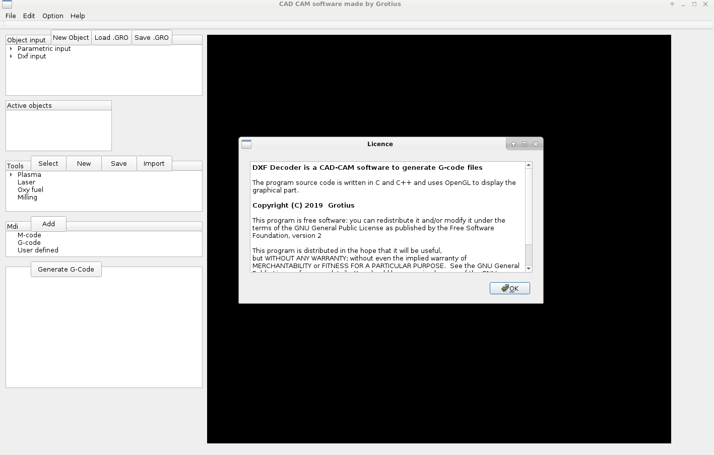
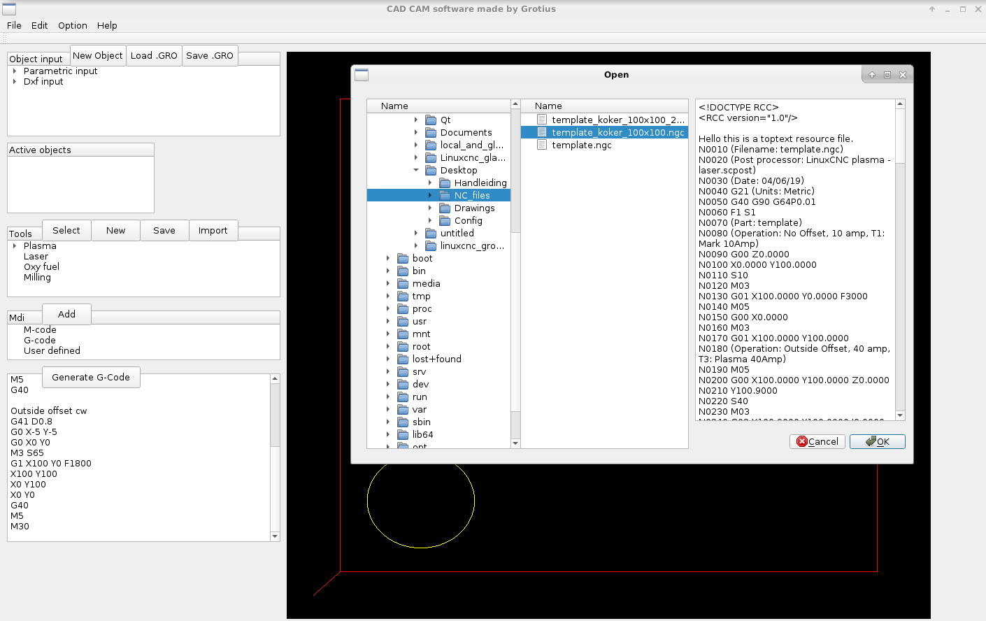
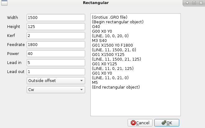
I spend some time making dialog's and a file open dialog is in progress.
Dialog example :
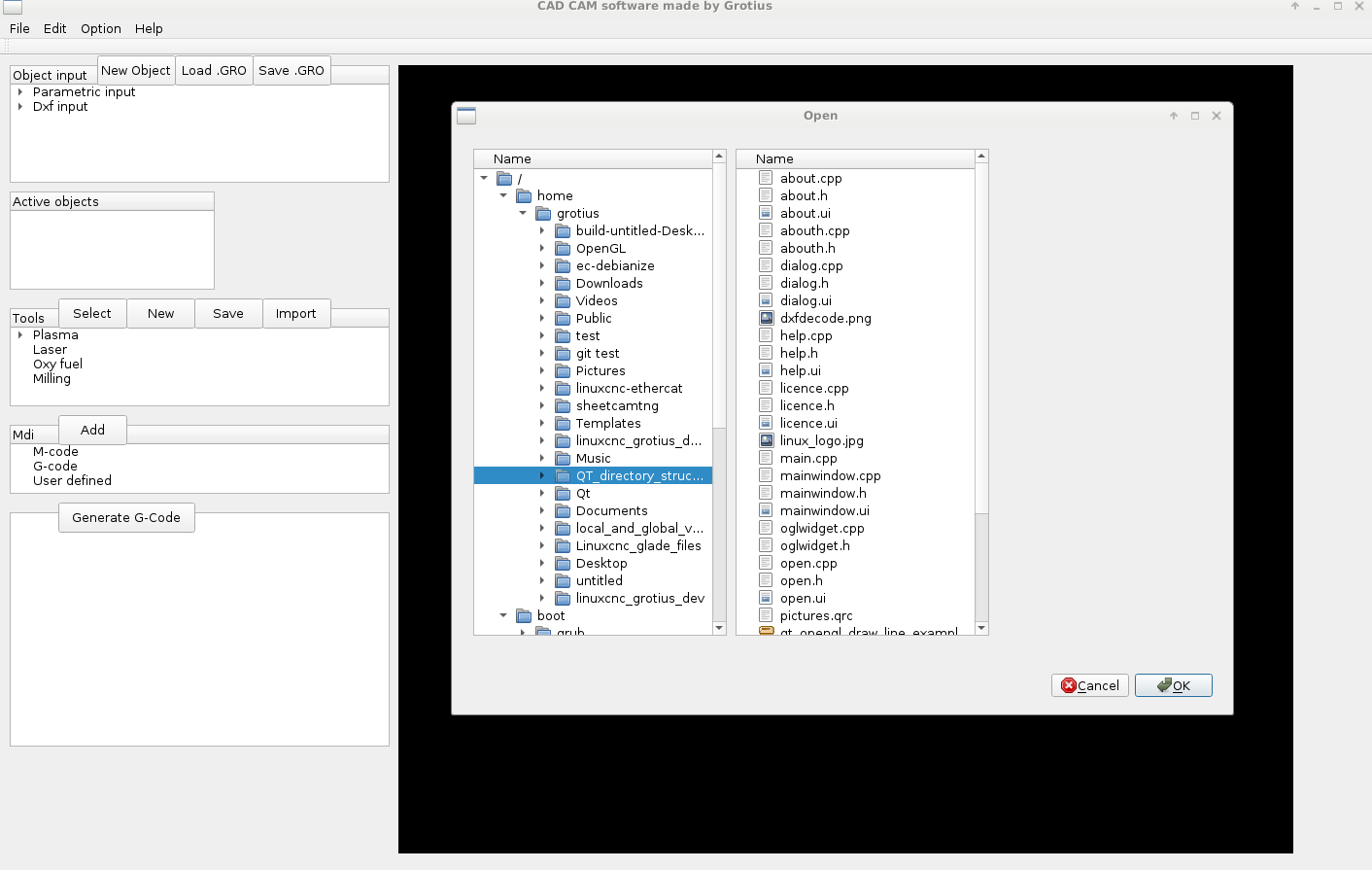
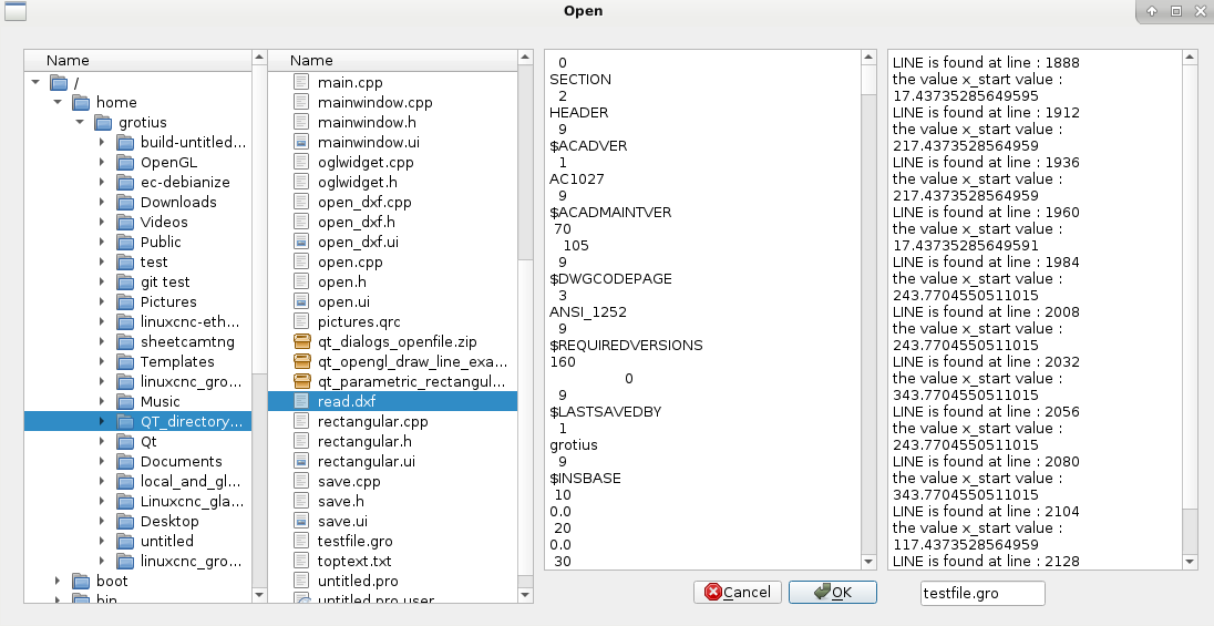
File open example, not finished :
All project files are attached.
To run the program unzip the untitled.zip and type in terminal : ./untitled
To make an extra ui screen or dialog. It takes some knowledge if you want to connect signals trough the menu bar.
I made a short line of how to achieve this.
But for me it was a quite hard experience to find out. Googling solved my looked over the eye problem.
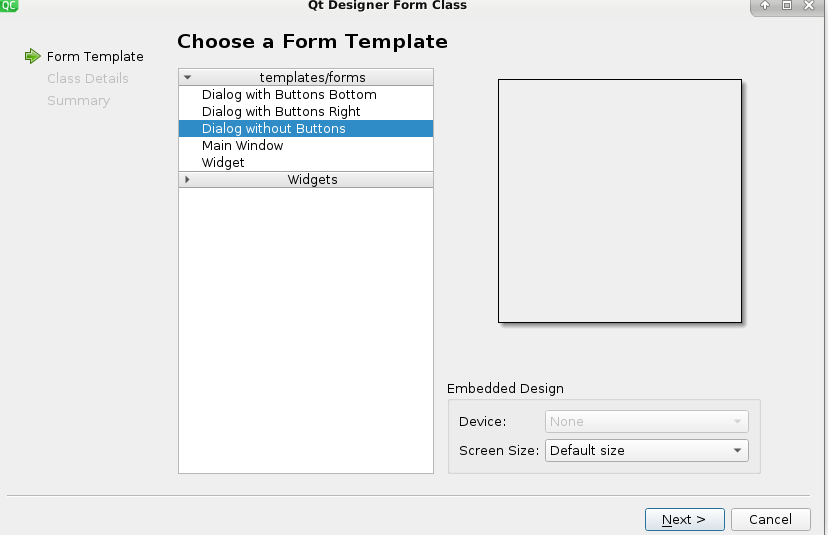
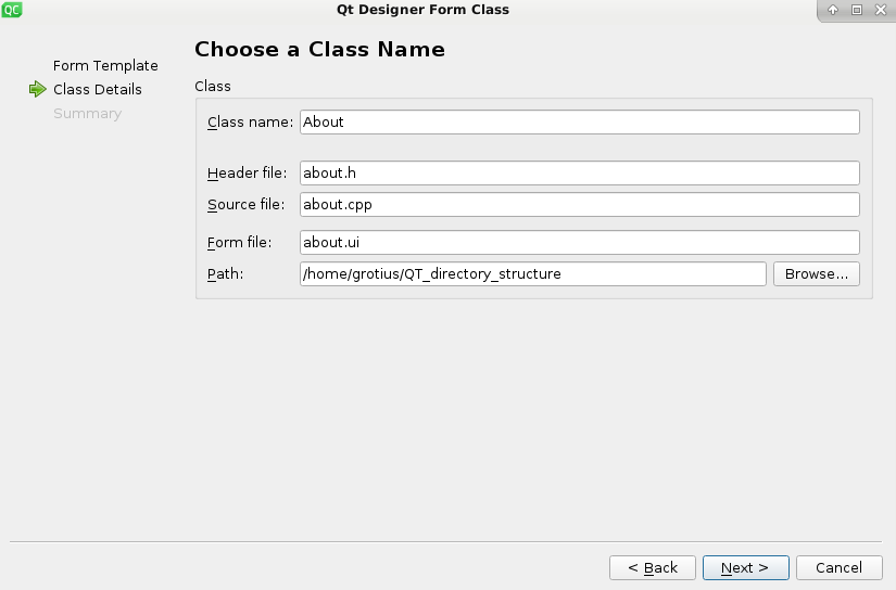
First make a new class.
In my case a blank window.
Provide a class name.
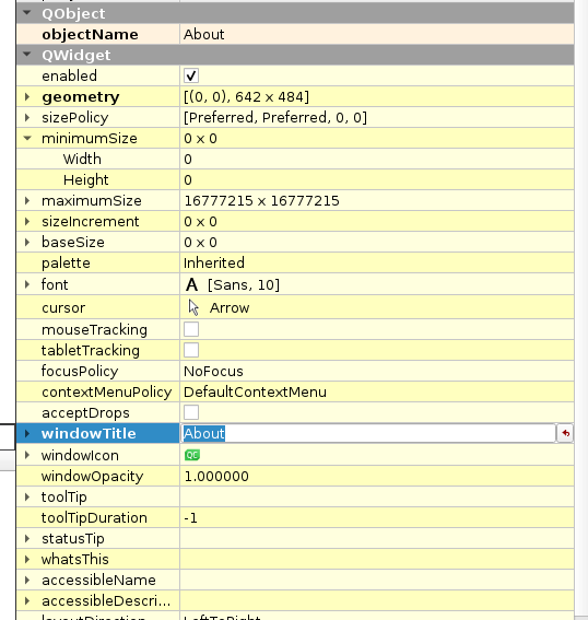
Name the window to your needs.
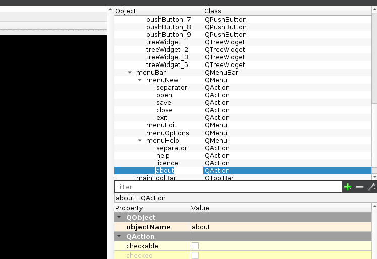
This is my main window menu bar. rename the links to your needs.
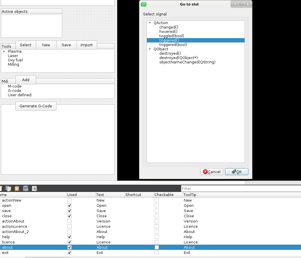
Menubar slots appear in the below screen. I was lost for this for a while.
This code will load your second screen
I made some progress. Founded out that Draftsight is written in QT also.
If you go to the 2019 version. It's directer during making a drawing. During making a drawing the responce is directer.
When the file loader and saver dialogs are ready, i am going to think about how to set up the .gro file structure.
That is a dxf and ngc inluded in one file. Hope to do a little magic by the time i get there.
For the one's who are thinking where are the parametric input's? They are behind the OpenGL screen at the moment.
I need to integrate them in a input pop up window soon !!!
Thermal Dynamics has sent me an okey to integrate the cut chart's open source. I am waiting for Hypertherm. That can take some time.
Last edit: 16 Jun 2019 23:30 by Grotius.
Please Log in or Create an account to join the conversation.
- Grotius
-
 Topic Author
- Offline
- Platinum Member
-

Less
More
- Posts: 2419
- Thank you received: 2345
18 Jun 2019 15:33 #137199
by Grotius
Replied by Grotius on topic QT C++ code samples
Little project update,
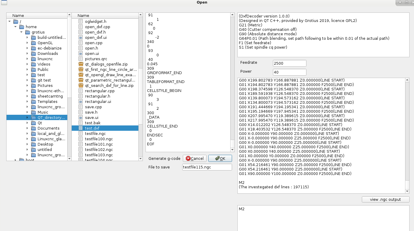
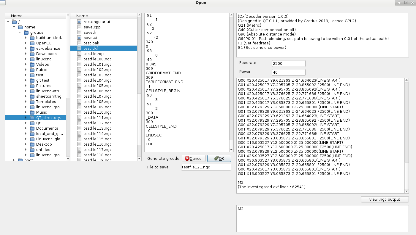
The custom file dialog is loading nice, it works like a file explorer, it display's directory structure at the left panel and file structure at the right panel. A nice advantage is, it does a textfile preview of the file you want to load.
I think i will add a OpenGL preview function to this open file dialog in a later stadium.
When the dxf to g-code function's are integrated, that would be quite easy to do.
So far so good. Up to the next item.
Attachments:
Please Log in or Create an account to join the conversation.
- Grotius
-
 Topic Author
- Offline
- Platinum Member
-

Less
More
- Posts: 2419
- Thank you received: 2345
19 Jun 2019 21:03 - 19 Jun 2019 21:17 #137309
by Grotius
Replied by Grotius on topic QT C++ code samples
Little project update.
I was looking to combine a .ngc file (g-code) and a dxf file (cad file) at once, output could be a file .gro file.
I mentioned before linuxcnc has no problem's with reading () sign's trough program execution.
But i have to find a solution or make a filter to load in a .gro file into cad program's.
The .gro file can include also nesting parameters, what can be very handy in future.
My first idea after this test tonight is that we can make a inverse g-code generator.
A generator for saving a g-code file back into dxf format.
The parametric input example :
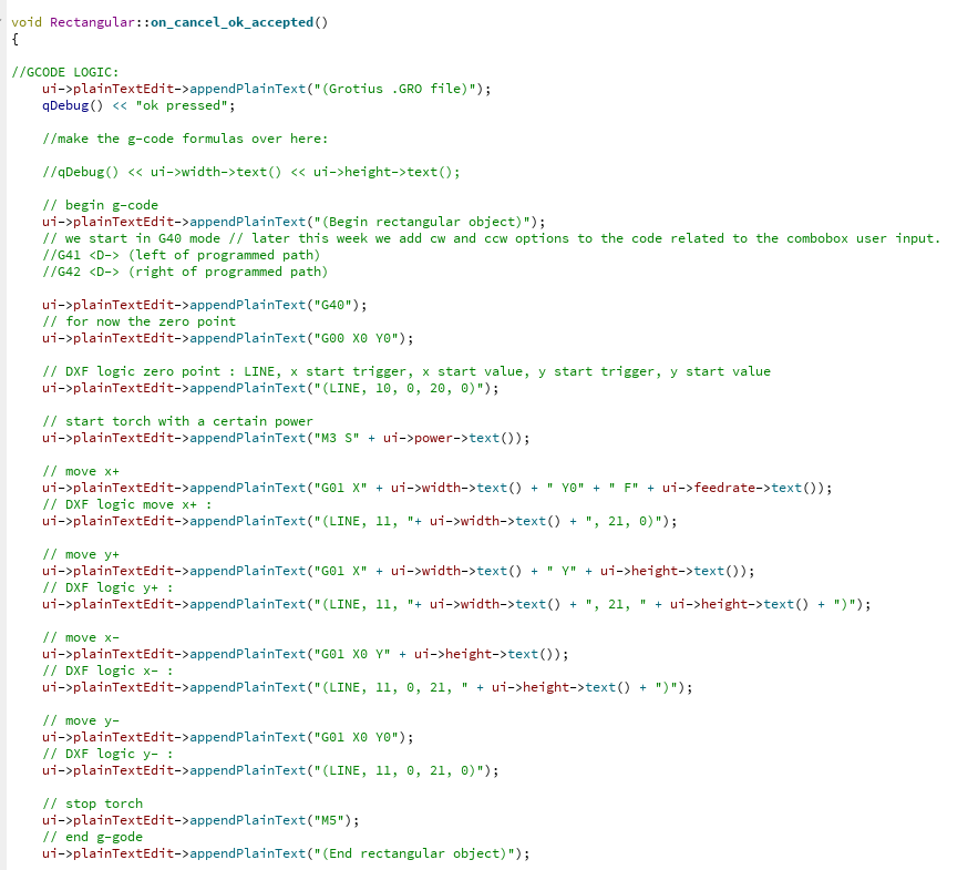
The C++ code example :
The simplest way is to have different file format output's and keep the output file filter inside the provided C++ program.
Also for a automated Reverse engeneering of a g-code file into a dxf file, the simplest way is to keep the calculation's inside the C++ program.
Attachments:
Last edit: 19 Jun 2019 21:17 by Grotius.
Please Log in or Create an account to join the conversation.
- Grotius
-
 Topic Author
- Offline
- Platinum Member
-

Less
More
- Posts: 2419
- Thank you received: 2345
20 Jun 2019 15:30 - 20 Jun 2019 16:32 #137393
by Grotius
Replied by Grotius on topic QT C++ code samples
Little project update.
In my first c code project i had made some nice c code that load's the dxf file line by line and make a ngc file and print the OpenGL output to a Glut window in GTK+. I did not like Glut because it is a pop up opengl window. And GTK+ was just not loving a widget like OpenGL. So i switched to QT C++ a few weeks ago. And now i finally can go fast !!
My previous written C code has to be conversed from C code to C++ code.
So i started with this today. And it works quite easy.
In the Dxf2Gcode program, goto menubar =>File => Open.
Select your dxf drawing and your output will be saved in the directory the dxf file lives in, you can specify the program .gro output name.
For now i started with the dxf LINE. All others like Circle, Arc, Polyline, etc. will be integrated coming day's.
A sample to view the difference in coding C and C++
In this code example i am searching for the word "LINE" and i exclude some words where line is inside the word.
Conventional C coding :
C++ QT coding :
You see, the C++ coding is easyer and quicker to do. I now work with classes, this works nice.
Attached the QT project files.
To run in qt, open the .pro file
To run the program, unzip the attached untitlded.zip file and type in terminal : ./untitled
=> select your dxf file at your pc and see what happen's
=> menubar => file => open => select dxf
=> the .gro output will be saved in the same directory where the dxf lives in
Trough exceeding the forum file size, the attached file untitled.zip 1.8mb cannot be uploaded here.
Last edit: 20 Jun 2019 16:32 by Grotius.
Please Log in or Create an account to join the conversation.
- Grotius
-
 Topic Author
- Offline
- Platinum Member
-

Less
More
- Posts: 2419
- Thank you received: 2345
23 Jun 2019 15:20 - 23 Jun 2019 15:40 #137657
by Grotius
Replied by Grotius on topic QT C++ code samples
Integrated the Circle and Arc's today into the QT C++ code and tested in Linuxcnc axis.
The line's where already ingrated so far. I just updated some outdated C code today to stay at maximum precision.
The project file's and program executable is becoming to big to upload. So i find a solution for this.
To download the executable file, stay's here for 1 week : we.tl/t-rqgkzb1tkM
With this file you can do already a few automated step's related to dxf to g-code.
Please test how many line's this program can investegate without being overloaded.....
If something get's overloaded, it's problably the QT plaintextview widget that display's the dxf source file line by line.
M3 and M5 are not integrated yet.
Next item to do is integrate the cad Polyline's, to be continued.
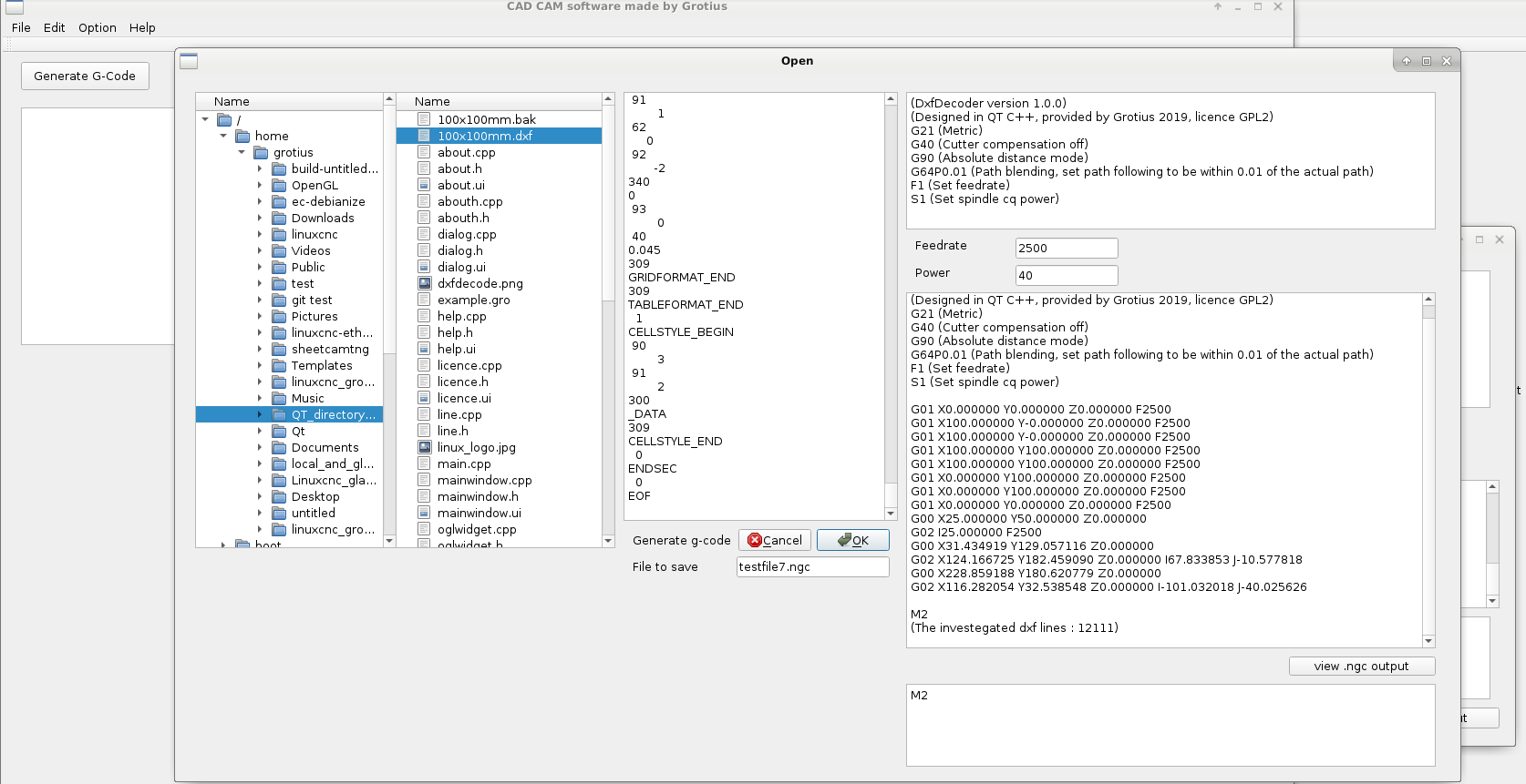
Select : File => open => select your dxf file and click OK. (wait a few second's until it appear's, the progress bar is not available yet)
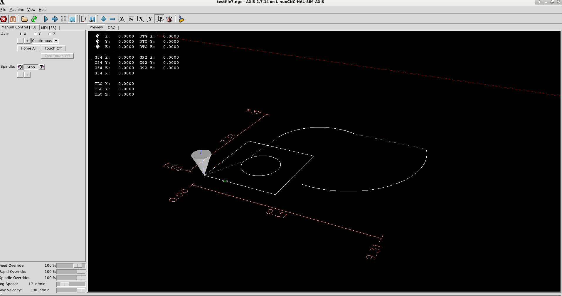
Then you can view code by clicking view code. Test your file in Linuxcnc for output.
If you downloaded the executable file, unzip and type in terminal : ./untitled
Program view to transform the dxf into ngc :
Axis output ngc code view :
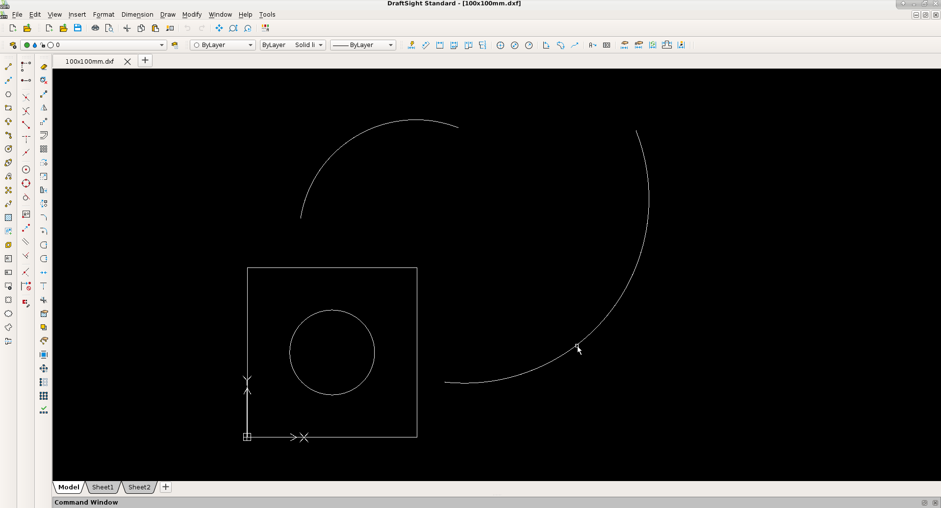
The cad program view :
Later on, when i have integrated more, and more, the Dxf2Gcode get's the updated OpenGL view.
Compatible i think up to draftsight 2019 dxf format at the moment.
So far so good.
Attachments:
Last edit: 23 Jun 2019 15:40 by Grotius.
The following user(s) said Thank You: phillc54
Please Log in or Create an account to join the conversation.
- Grotius
-
 Topic Author
- Offline
- Platinum Member
-

Less
More
- Posts: 2419
- Thank you received: 2345
24 Jun 2019 21:31 - 24 Jun 2019 22:16 #137753
by Grotius
Replied by Grotius on topic QT C++ code samples
I did not realise the DxfDecoder is fully 3d.
But during writing of the C and C++ code i used all x, y, z parameters. We are lucky that this is done. I did not test this
3d function before. But it works !
Trough the 3d, we can do 3d lead in's, and try to cut little holes with a spiral 3d technique. And for milling it's also handy to
use 3d g-code.
At the moment the basic line, circle, arc are working. Polyline is almost done. Spline is difficult.
If you draw the cad drawing like the preview. It works quite nice for a free program.
I have to do more testing, etc. But everytime i see a bug. I update the code.
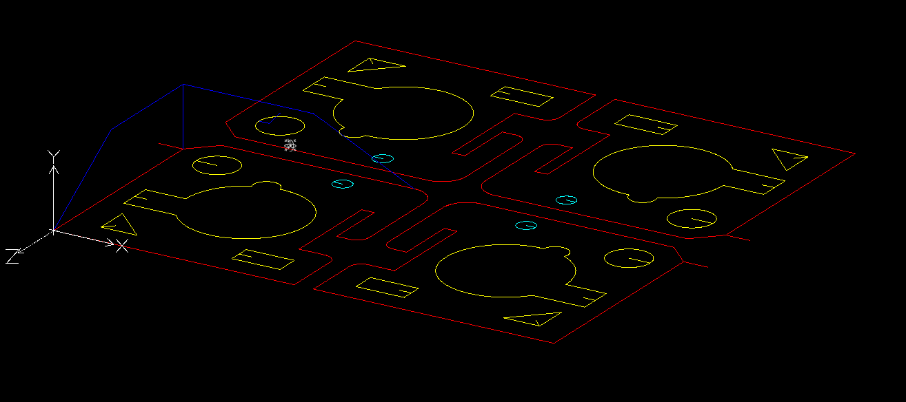
Example of 3d cad drawing. The blue lines are the 3d traject.
Look at the option for special lead in, in the hole, blue line...
I have the idea to define the dxf drawing with colors. I look at this option coming day's.
Red = outside offset
Yellow = inside offset
Cyan = slower
The linuxcnc output :
The dxfdecoder screen, not finished. Look at the dxf lines.... pff... more then 197000 lines are processed in about 5 seconds.
Todo : sorting the g-code lines into closed contours, this is quite difficult and can take a lot of time. It looks like make a formule
for solving a colered cubic game.
Todo : add logic about G41 and G42, i think based on the used cad colors. This is user friendly, and will simplify coding a lot.
To run the program, follow this download link, it stay's here one week : we.tl/t-xhbTIJqyYM
unzip and type in terminal : ./untitled
Attachments:
Last edit: 24 Jun 2019 22:16 by Grotius.
Please Log in or Create an account to join the conversation.
- Grotius
-
 Topic Author
- Offline
- Platinum Member
-

Less
More
- Posts: 2419
- Thank you received: 2345
24 Jun 2019 23:11 - 24 Jun 2019 23:13 #137759
by Grotius
Replied by Grotius on topic QT C++ code samples
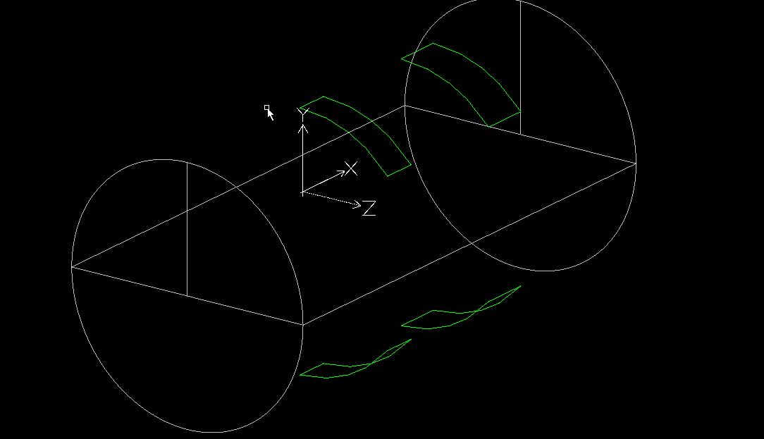
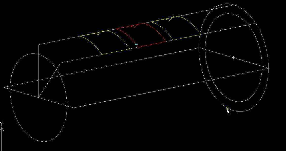
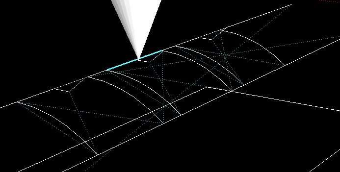
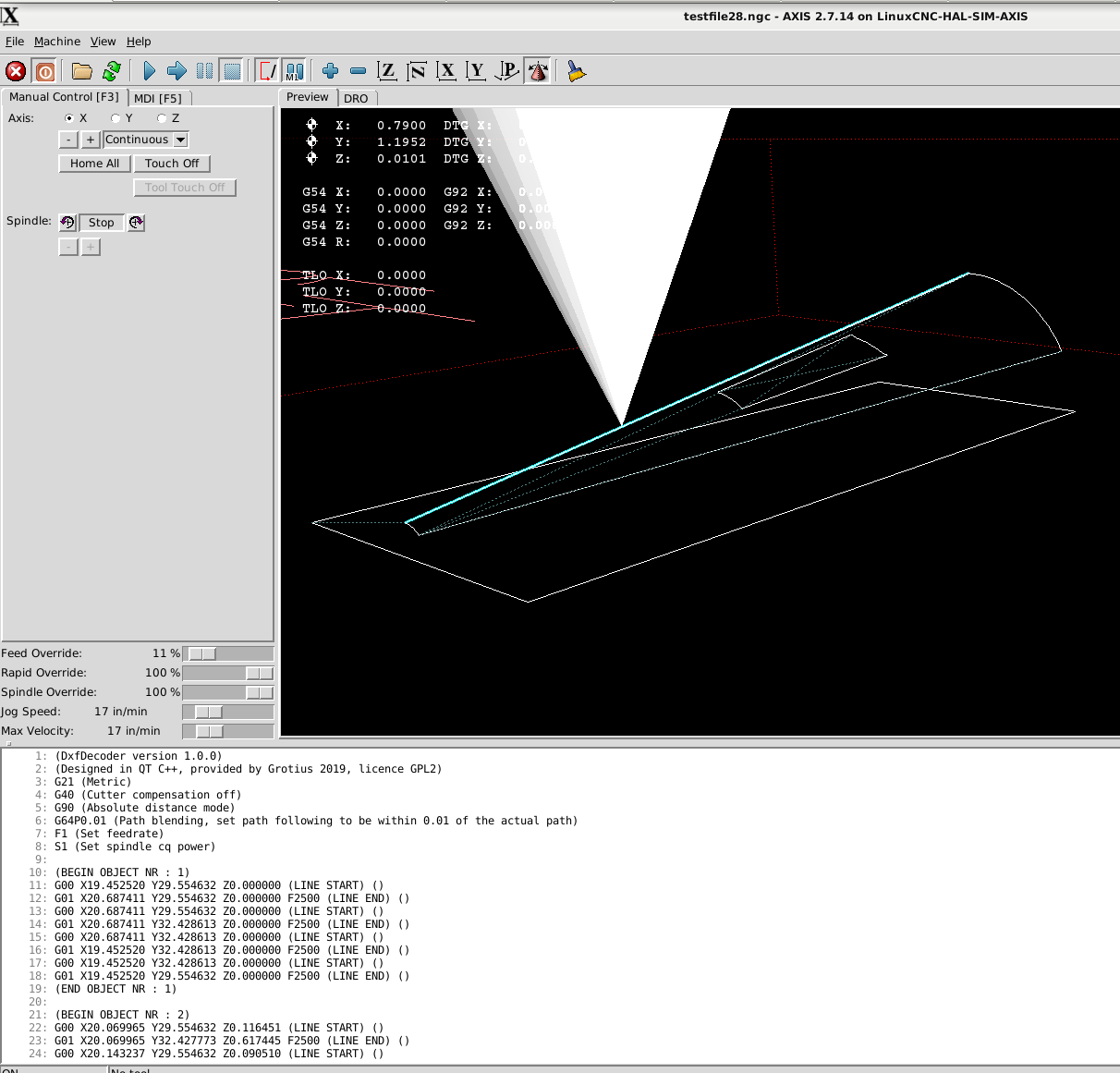
A nice 3d tube cutting example.
This is special because the torch will stay in vertical position related to the tube.
It fit's a rectangular tube straight trough the tube profile. This is important for inox balcony profiles.
They must fit tight.
The 3d tube drawing :
the linux output :
the dxfdecoder output :
In the code i spotted a circle plane problem. So i will investegate this later on. I have to solve this in the C++ code i see.
Have to transform circle's and arc's into a other plane. I think i will make a calculation for this later on.
At this moment, for this example i have used only lines and no circles and arc's into the g-code.
The g-code that you can load in axis simulation :
So far so good.
This is special because the torch will stay in vertical position related to the tube.
It fit's a rectangular tube straight trough the tube profile. This is important for inox balcony profiles.
They must fit tight.
The 3d tube drawing :
the linux output :
the dxfdecoder output :
In the code i spotted a circle plane problem. So i will investegate this later on. I have to solve this in the C++ code i see.
Have to transform circle's and arc's into a other plane. I think i will make a calculation for this later on.
At this moment, for this example i have used only lines and no circles and arc's into the g-code.
The g-code that you can load in axis simulation :
Warning: Spoiler!
(DxfDecoder version 1.0.0)
(Designed in QT C++, provided by Grotius 2019, licence GPL2)
G21 (Metric)
G40 (Cutter compensation off)
G90 (Absolute distance mode)
G64P0.01 (Path blending, set path following to be within 0.01 of the actual path)
F1 (Set feedrate)
S1 (Set spindle cq power)

G00 X0.000000 Y0.000000 Z-12.500000(LINE START)
G01 X50.000000 Y0.000000 Z-12.500000 F2500(LINE END)
G00 X50.000000 Y0.000000 Z-12.500000(LINE START)
G01 X50.000000 Y25.000000 Z-12.500000 F2500(LINE END)
G00 X50.000000 Y25.000000 Z-12.500000(LINE START)
G01 X0.000000 Y25.000000 Z-12.500000 F2500(LINE END)
G00 X0.000000 Y25.000000 Z-12.500000(LINE START)
G01 X0.000000 Y0.000000 Z-12.500000 F2500(LINE END)
G00 X16.903527 Y12.500000 Z0.000000(LINE START)
G01 X16.903527 Y9.621363 Z-0.335977 F2500(LINE END)
G00 X16.903527 Y9.621363 Z-0.335977(LINE START)
G01 X16.903527 Y7.295705 Z-1.134908 F2500(LINE END)
G00 X16.903527 Y7.295705 Z-1.134908(LINE START)
G01 X16.903527 Y5.376625 Z-2.228314 F2500(LINE END)
G00 X16.903527 Y5.376625 Z-2.228314(LINE START)
G01 X16.903527 Y3.035873 Z-4.334199 F2500(LINE END)
G00 X36.903527 Y12.500000 Z0.000000(LINE START)
G01 X36.903527 Y9.621363 Z-0.335977 F2500(LINE END)
G00 X36.903527 Y9.621363 Z-0.335977(LINE START)
G01 X36.903527 Y7.295705 Z-1.134908 F2500(LINE END)
G00 X36.903527 Y7.295705 Z-1.134908(LINE START)
G01 X36.903527 Y5.376625 Z-2.228314 F2500(LINE END)
G00 X36.903527 Y5.376625 Z-2.228314(LINE START)
G01 X36.903527 Y3.035873 Z-4.334199 F2500(LINE END)
G00 X20.425017 Y12.500000 Z0.000000(LINE START)
G01 X20.425017 Y9.621363 Z-0.335977 F2500(LINE END)
G00 X20.425017 Y9.621363 Z-0.335977(LINE START)
G01 X20.425017 Y7.295705 Z-1.134908 F2500(LINE END)
G00 X20.425017 Y7.295705 Z-1.134908(LINE START)
G01 X20.425017 Y5.376625 Z-2.228314 F2500(LINE END)
G00 X20.425017 Y5.376625 Z-2.228314(LINE START)
G01 X20.425017 Y3.035873 Z-4.334199 F2500(LINE END)
G00 X32.079329 Y12.500000 Z0.000000(LINE START)
G01 X32.079329 Y9.621363 Z-0.335977 F2500(LINE END)
G00 X32.079329 Y9.621363 Z-0.335977(LINE START)
G01 X32.079329 Y7.295705 Z-1.134908 F2500(LINE END)
G00 X32.079329 Y7.295705 Z-1.134908(LINE START)
G01 X32.079329 Y5.376625 Z-2.228314 F2500(LINE END)
G00 X32.079329 Y5.376625 Z-2.228314(LINE START)
G01 X32.079329 Y3.035873 Z-4.334199 F2500(LINE END)
G00 X16.903527 Y12.500000 Z0.000000(LINE START)
G01 X20.425017 Y12.500000 Z0.000000 F2500(LINE END)
G00 X32.079329 Y12.500000 Z0.000000(LINE START)
G01 X36.903527 Y12.500000 Z0.000000 F2500(LINE END)
G00 X36.903527 Y3.035873 Z-4.334199(LINE START)
G01 X32.079329 Y3.035873 Z-4.334199 F2500(LINE END)
G00 X20.425017 Y3.035873 Z-4.334199(LINE START)
G01 X16.903527 Y3.035873 Z-4.334199 F2500(LINE END)
G00 X16.903527 Y12.500000 Z-25.000000(LINE START)
G01 X16.903527 Y9.621363 Z-24.664023 F2500(LINE END)
G00 X16.903527 Y9.621363 Z-24.664023(LINE START)
G01 X16.903527 Y7.295705 Z-23.865092 F2500(LINE END)
G00 X16.903527 Y7.295705 Z-23.865092(LINE START)
G01 X16.903527 Y5.376625 Z-22.771686 F2500(LINE END)
G00 X16.903527 Y5.376625 Z-22.771686(LINE START)
G01 X16.903527 Y3.035873 Z-20.665801 F2500(LINE END)
G00 X36.903527 Y12.500000 Z-25.000000(LINE START)
G01 X36.903527 Y9.621363 Z-24.664023 F2500(LINE END)
G00 X36.903527 Y9.621363 Z-24.664023(LINE START)
G01 X36.903527 Y7.295705 Z-23.865092 F2500(LINE END)
G00 X36.903527 Y7.295705 Z-23.865092(LINE START)
G01 X36.903527 Y5.376625 Z-22.771686 F2500(LINE END)
G00 X36.903527 Y5.376625 Z-22.771686(LINE START)
G01 X36.903527 Y3.035873 Z-20.665801 F2500(LINE END)
G00 X20.425017 Y12.500000 Z-25.000000(LINE START)
G01 X20.425017 Y9.621363 Z-24.664023 F2500(LINE END)
G00 X20.425017 Y9.621363 Z-24.664023(LINE START)
G01 X20.425017 Y7.295705 Z-23.865092 F2500(LINE END)
G00 X20.425017 Y7.295705 Z-23.865092(LINE START)
G01 X20.425017 Y5.376625 Z-22.771686 F2500(LINE END)
G00 X20.425017 Y5.376625 Z-22.771686(LINE START)
G01 X20.425017 Y3.035873 Z-20.665801 F2500(LINE END)
G00 X32.079329 Y12.500000 Z-25.000000(LINE START)
G01 X32.079329 Y9.621363 Z-24.664023 F2500(LINE END)
G00 X32.079329 Y9.621363 Z-24.664023(LINE START)
G01 X32.079329 Y7.295705 Z-23.865092 F2500(LINE END)
G00 X32.079329 Y7.295705 Z-23.865092(LINE START)
G01 X32.079329 Y5.376625 Z-22.771686 F2500(LINE END)
G00 X32.079329 Y5.376625 Z-22.771686(LINE START)
G01 X32.079329 Y3.035873 Z-20.665801 F2500(LINE END)
G00 X16.903527 Y12.500000 Z-25.000000(LINE START)
G01 X20.425017 Y12.500000 Z-25.000000 F2500(LINE END)
G00 X32.079329 Y12.500000 Z-25.000000(LINE START)
G01 X36.903527 Y12.500000 Z-25.000000 F2500(LINE END)
G00 X36.903527 Y3.035873 Z-20.665801(LINE START)
G01 X32.079329 Y3.035873 Z-20.665801 F2500(LINE END)
G00 X20.425017 Y3.035873 Z-20.665801(LINE START)
G01 X16.903527 Y3.035873 Z-20.665801 F2500(LINE END)

M2
(The investegated dxf lines : 62541)
So far so good.
Attachments:
Last edit: 24 Jun 2019 23:13 by Grotius.
The following user(s) said Thank You: chimeno
Please Log in or Create an account to join the conversation.
- Grotius
-
 Topic Author
- Offline
- Platinum Member
-

Less
More
- Posts: 2419
- Thank you received: 2345
25 Jun 2019 22:19 - 26 Jun 2019 00:33 #137830
by Grotius
Replied by Grotius on topic QT C++ code samples
Today i added code for recognizing closed contours, i used the Qlist library to make array's.
Qlist array's are nice. Maybe i use Hash array's some day. They are allocating memory different and can be faster when
using huge files. The Hash array is not switching allocated memory. The Hash array can have memory all around, so it does not have to change the whole Qlist one memory line down. Maybe the name Hash is allocated to Bitcoin.
The program now specifies a inside offset, a outside offset and no offset (open contours).
It's working for line function's at the moment. I have to integrate it also for circle and arc's.
My software vision about the program work flow can make a little change coming day's.
I write the textfile output in one sequence at this moment, very fast, but a very hard to do for this program.
I will try to stay at this workflow, but when we use for example auto-nesting we have to change g-code object's up or down in
the g-code list. A tiny example is "keep parts together", rotate them an fit them in a certain area.
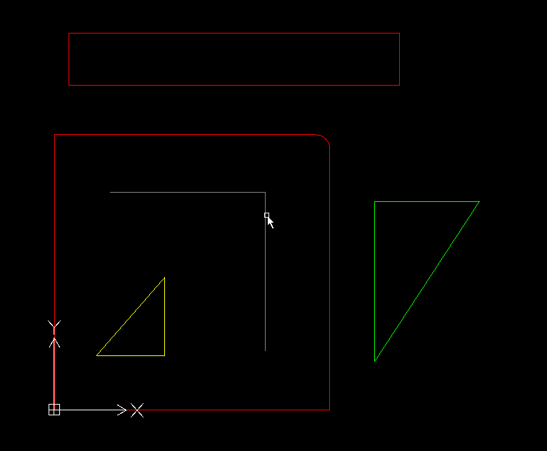
The cad drawing :
Red = outside offset
Yellow = inside offset
Grey = no offset
Green = can be marking or what we want to do...
Cyan = slower
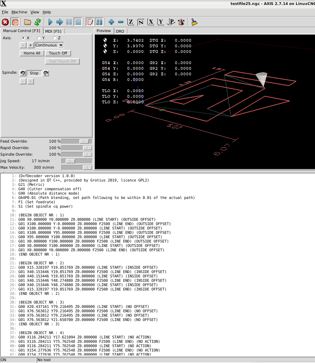
The linuxcnc output :
If you look at the g-code output you see double g-code lines, G0 and G1. So far this is no problem.
This can be deleted, but i can use this for inversing the cw to
ccw movement at the object. They will be deleted when the G41.1 and G42.1 are integrated.
The idea is to make for each object, one array.
For a example A little C++ code how to swap an array (Qlist) I have to write this code soon. But i write now how to do it, before
writing actual C++ code...
This is the vision :
Array 1 = Object 1 (gcode object, see picture)
Array 2 = Object 2 (gcode object, can be 1000 lines of code, no problem for the array's)
We can use multiple parameters for each array....
We put value's in the array's...
Array 1 = x_start, y_start, z_start, x_end, y_end, z_end, cw, ccw
To inverse from clockwise (cw) to counterclockwise (ccw). It's a kind of interpolation, a very easy way of this kind...
If we use a swap function from the Qlist C++ library we can swap (change) the x_start value with the x_end value,
when this is done for all parameters, we have inverted the cutting path from cw to ccw. The swap function is very fast.
Array 1 = x_start(100), y_start, z_start, x_end(50), y_end, z_end, cw(1), ccw(0)
after swap :
Array 1 = x_start(50), y_start, z_start, x_end(100), y_end, z_end, cw(0), ccw(1)
For tubes, it's handy to have defined inside, outside and no offset's for each tube.
The used cad color lines are perfect to define this.
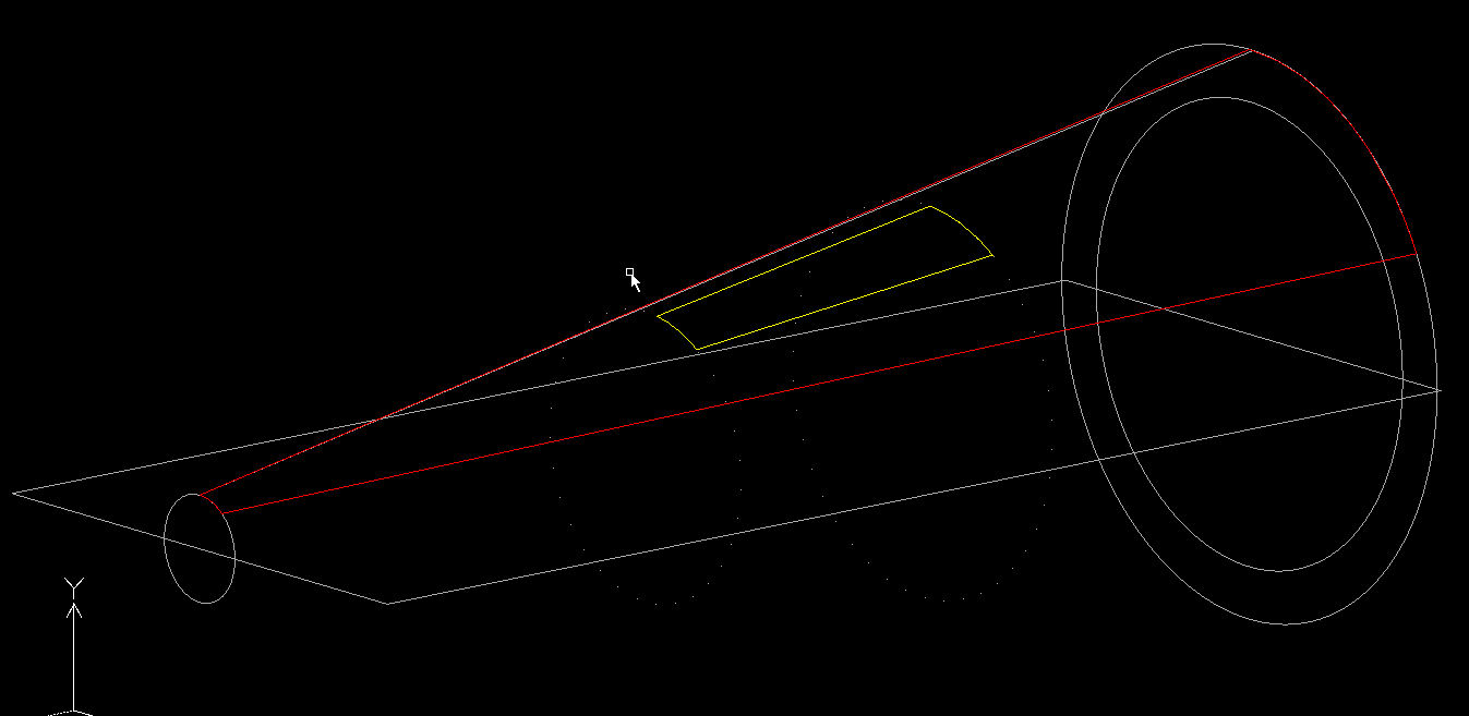
3d lead in.
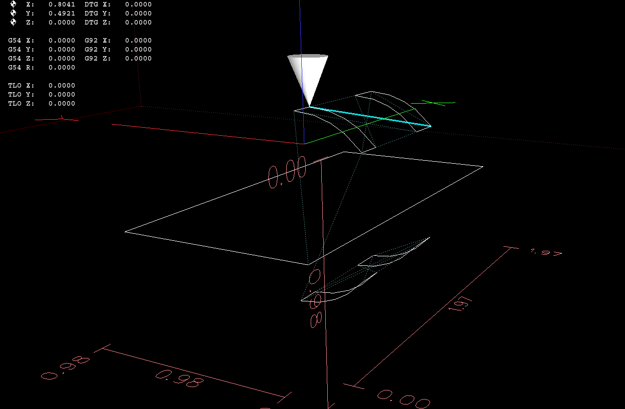
Cutting a part of a space craft with a free program
It's the top window of the space craft, a 3d cone shape...
So far so good.
Qlist array's are nice. Maybe i use Hash array's some day. They are allocating memory different and can be faster when
using huge files. The Hash array is not switching allocated memory. The Hash array can have memory all around, so it does not have to change the whole Qlist one memory line down.
The program now specifies a inside offset, a outside offset and no offset (open contours).
It's working for line function's at the moment. I have to integrate it also for circle and arc's.
My software vision about the program work flow can make a little change coming day's.
I write the textfile output in one sequence at this moment, very fast, but a very hard to do for this program.
I will try to stay at this workflow, but when we use for example auto-nesting we have to change g-code object's up or down in
the g-code list. A tiny example is "keep parts together", rotate them an fit them in a certain area.
The cad drawing :
Red = outside offset
Yellow = inside offset
Grey = no offset
Green = can be marking or what we want to do...
Cyan = slower
The linuxcnc output :
If you look at the g-code output you see double g-code lines, G0 and G1. So far this is no problem.
This can be deleted, but i can use this for inversing the cw to
ccw movement at the object. They will be deleted when the G41.1 and G42.1 are integrated.
The idea is to make for each object, one array.
For a example A little C++ code how to swap an array (Qlist) I have to write this code soon. But i write now how to do it, before
writing actual C++ code...
This is the vision :
Array 1 = Object 1 (gcode object, see picture)
Array 2 = Object 2 (gcode object, can be 1000 lines of code, no problem for the array's)
We can use multiple parameters for each array....
We put value's in the array's...
Array 1 = x_start, y_start, z_start, x_end, y_end, z_end, cw, ccw
To inverse from clockwise (cw) to counterclockwise (ccw). It's a kind of interpolation, a very easy way of this kind...
If we use a swap function from the Qlist C++ library we can swap (change) the x_start value with the x_end value,
when this is done for all parameters, we have inverted the cutting path from cw to ccw. The swap function is very fast.
Array 1 = x_start(100), y_start, z_start, x_end(50), y_end, z_end, cw(1), ccw(0)
after swap :
Array 1 = x_start(50), y_start, z_start, x_end(100), y_end, z_end, cw(0), ccw(1)
For tubes, it's handy to have defined inside, outside and no offset's for each tube.
The used cad color lines are perfect to define this.
3d lead in.
Cutting a part of a space craft with a free program
It's the top window of the space craft, a 3d cone shape...
So far so good.
Attachments:
Last edit: 26 Jun 2019 00:33 by Grotius.
The following user(s) said Thank You: chimeno
Please Log in or Create an account to join the conversation.
Time to create page: 0.763 seconds

