- Configuring LinuxCNC
- Advanced Configuration
- Dual PID loops with motor encoder + scale encoder per axis
Dual PID loops with motor encoder + scale encoder per axis
- TangentAudio
- Offline
- Premium Member
-

Less
More
- Posts: 97
- Thank you received: 29
09 Apr 2024 14:15 - 09 Apr 2024 14:28 #297865
by TangentAudio
Dual PID loops with motor encoder + scale encoder per axis was created by TangentAudio
Greetings,
I'm working on a new conversion project, modernizing an old Bridgeport Series 1 2HP that has a working Prototrak Plus system on it. For "phase 1" of the project I am keeping the original Trak servo motors/drives/encoders and the Trak "wheel" style encoders for table position. The machine has ballscrews, though they are a bit worn and have some backlash. I know this isn't ideal and may present some problems, but I hope to tackle that later. My goal is to get it up and running for close to zero cost initially, then figure out what I want to improve later.
My past conversions have all been open-loop stepper systems, and while I'm quite comfortable with LinuxCNC down to the programming level, closed loop config and tuning with LinuxCNC is new to me. I've been focused on getting one axis working first. I was able to at least get a basic tune on a single loop using just the motor encoder. But I'd like to take the next step and use the axis position encoders in a dual loop setup to improve positional accuracy.
I'm using a Mesa 7i43 parallel port FPGA card that I had left over from my first CNC conversion 12+ years ago. I designed and hand-wired a board to handle the differential signal conversion to/from the servo drives and encoders. I've got that all working just fine on the bench - all of the encoders and servo outputs work through Hostmot2 and HAL as expected.
I did a bunch of searching on the forum but there seems to be fairly sparse info on this topic. I followed the guide that's on the wiki , but it's also a bit light on details. I've got a rough config put together based on the steps in that guide, but I know it still has some problems and I could use a more experienced set of eyes. My controls engineering class was almost 30 years ago at this point (!), and while I do have some basic experience and understanding of PID control, I'm getting a little ahead of my skis on this dual loop implementation.
Happy to share full configs, but I figured I'd start with just the X axis snippets. My guess is my config problems are in the feedback part near the bottom of the HAL config, that's where the wiki guide seemed most vague.
Thanks!
Here's the INI:
and the HAL:
I'm working on a new conversion project, modernizing an old Bridgeport Series 1 2HP that has a working Prototrak Plus system on it. For "phase 1" of the project I am keeping the original Trak servo motors/drives/encoders and the Trak "wheel" style encoders for table position. The machine has ballscrews, though they are a bit worn and have some backlash. I know this isn't ideal and may present some problems, but I hope to tackle that later. My goal is to get it up and running for close to zero cost initially, then figure out what I want to improve later.
My past conversions have all been open-loop stepper systems, and while I'm quite comfortable with LinuxCNC down to the programming level, closed loop config and tuning with LinuxCNC is new to me. I've been focused on getting one axis working first. I was able to at least get a basic tune on a single loop using just the motor encoder. But I'd like to take the next step and use the axis position encoders in a dual loop setup to improve positional accuracy.
I'm using a Mesa 7i43 parallel port FPGA card that I had left over from my first CNC conversion 12+ years ago. I designed and hand-wired a board to handle the differential signal conversion to/from the servo drives and encoders. I've got that all working just fine on the bench - all of the encoders and servo outputs work through Hostmot2 and HAL as expected.
I did a bunch of searching on the forum but there seems to be fairly sparse info on this topic. I followed the guide that's on the wiki , but it's also a bit light on details. I've got a rough config put together based on the steps in that guide, but I know it still has some problems and I could use a more experienced set of eyes. My controls engineering class was almost 30 years ago at this point (!), and while I do have some basic experience and understanding of PID control, I'm getting a little ahead of my skis on this dual loop implementation.
Happy to share full configs, but I figured I'd start with just the X axis snippets. My guess is my config problems are in the feedback part near the bottom of the HAL config, that's where the wiki guide seemed most vague.
Thanks!
Here's the INI:
#******************************************
[AXIS_X]
MAX_VELOCITY = 2.0
MAX_ACCELERATION = 10.0
MIN_LIMIT = -12.0
MAX_LIMIT = 12.0

[JOINT_0]
TYPE = LINEAR
HOME = 0.0
FERROR = 0.025
MIN_FERROR = 0.008
MAX_VELOCITY = 2.0
MAX_ACCELERATION = 10.0
P = 650
I = 0
D = 25
FF0 = 0
FF1 = 0.1
FF2 = 0.01
BIAS = 0
DEADBAND = 2e-06
MAX_OUTPUT = 10
ENCODER_MOTOR_SCALE = 27940
ENCODER_LINEAR_SCALE = 5080
OUTPUT_SCALE = 10
MIN_LIMIT = -12.0
MAX_LIMIT = 12.0
HOME_OFFSET = 0.0
HOME_SEQUENCE = 2
#******************************************
and the HAL:
#*******************
#  AXIS X JOINT 0
#*******************

# PWM Generator
# The ProtoTrak Plus servo drives use offset mode PWM, 50% duty = off, 0% duty = -100%, 100% duty = +100%
# HostMot2 PWM generator supports this natively by setting offset-mode to true
setp   [HMOT](CARD0).pwmgen.00.output-type 1
setp   [HMOT](CARD0).pwmgen.00.offset-mode true
setp   [HMOT](CARD0).pwmgen.00.scale  [JOINT_0]OUTPUT_SCALE

# Velocity Loop (P, D, FF1)
setp   pid.vx.Pgain     [JOINT_0]P
setp   pid.vx.Igain      0
setp   pid.vx.Dgain     [JOINT_0]D
setp   pid.vx.bias      [JOINT_0]BIAS
setp   pid.vx.FF0       [JOINT_0]FF0
setp   pid.vx.FF1       [JOINT_0]FF1
setp   pid.vx.FF2       [JOINT_0]FF2
setp   pid.vx.deadband  [JOINT_0]DEADBAND
setp   pid.vx.maxoutput [JOINT_0]MAX_OUTPUT
setp   pid.vx.error-previous-target true

# Position Loop (I only)
setp   pid.px.Pgain     0
setp   pid.px.Igain     [JOINT_0]I
setp   pid.px.Dgain     0
setp   pid.px.bias      0
setp   pid.px.FF0       0
setp   pid.px.FF1       0
setp   pid.px.FF2       0
setp   pid.px.deadband  [JOINT_0]DEADBAND
setp   pid.px.maxoutput [JOINT_0]MAX_OUTPUT
setp   pid.px.error-previous-target true
# Sum output of the two PID loops together to produce the PWM output signal
net x-output-motor pid.vx.output <= sum2.x.in0
net x-output-linear pid.px.output <= sum2.x.in1
net x-output <= sum2.x.out => [HMOT](CARD0).pwmgen.00.value

# Motor encoder
setp    [HMOT](CARD0).encoder.00.counter-mode 0
setp    [HMOT](CARD0).encoder.00.filter 1
setp    [HMOT](CARD0).encoder.00.index-invert 0
setp    [HMOT](CARD0).encoder.00.index-mask 0
setp    [HMOT](CARD0).encoder.00.index-mask-invert 0
setp    [HMOT](CARD0).encoder.00.scale  [JOINT_0]ENCODER_MOTOR_SCALE

# Axis scale encoder
setp    [HMOT](CARD0).encoder.02.counter-mode 0
setp    [HMOT](CARD0).encoder.02.filter 1
setp    [HMOT](CARD0).encoder.02.index-invert 0
setp    [HMOT](CARD0).encoder.02.index-mask 0
setp    [HMOT](CARD0).encoder.02.index-mask-invert 0
setp    [HMOT](CARD0).encoder.02.scale  [JOINT_0]ENCODER_LINEAR_SCALE

# Neither of the ProtoTrak encoders have index signals, should this always be forced off?
net x-index-enable           joint.0.index-enable  <=>  [HMOT](CARD0).encoder.00.index-enable [HMOT](CARD0).encoder.02.index-enable
net x-index-enable       => pid.vx.index-enable pid.px.index-enable

# Velocity and position feedback into the PIDs
net x-motor-fb                  pid.vx.feedback <= [HMOT](CARD0).encoder.00.position => joint.0.motor-pos-fb
net x-linear-fb                 pid.px.feedback <= [HMOT](CARD0).encoder.02.position

# Home / limit switch signals - none yet.
net x-home-sw                 => joint.0.home-sw-in
net x-neg-limit            => joint.0.neg-lim-sw-in
net x-pos-limit            => joint.0.pos-lim-sw-in
Attachments:
Last edit: 09 Apr 2024 14:28 by TangentAudio.
Please Log in or Create an account to join the conversation.
- TangentAudio
- Offline
- Premium Member
-
Less
More
- Posts: 97
- Thank you received: 29
09 Apr 2024 14:35 #297867
by TangentAudio
Replied by TangentAudio on topic Dual PID loops with motor encoder + scale encoder per axis
My work-in-progress full configs are on github.
github.com/tangentaudio/linuxcnc-bridgep...n/configs/bridgeport
github.com/tangentaudio/linuxcnc-bridgep...n/configs/bridgeport
Please Log in or Create an account to join the conversation.
- TangentAudio
- Offline
- Premium Member
-
Less
More
- Posts: 97
- Thank you received: 29
09 Apr 2024 20:22 - 09 Apr 2024 20:23 #297872
by TangentAudio
Replied by TangentAudio on topic Dual PID loops with motor encoder + scale encoder per axis
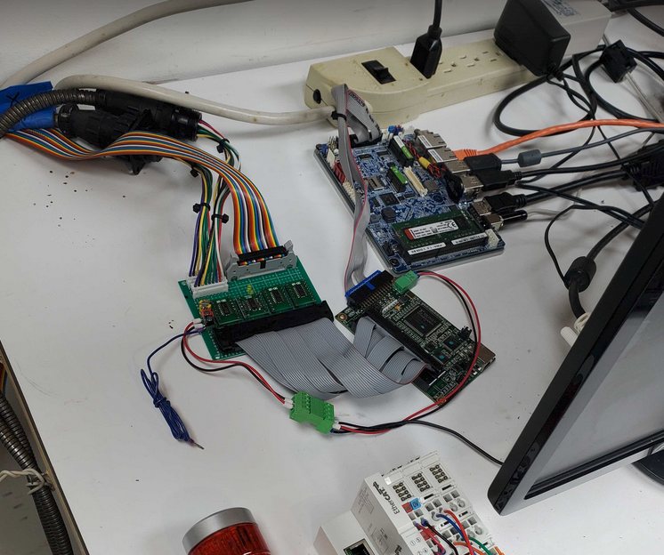
Just for fun, here are some of the first moves it made when I got a very rough tuning on a single loop working. Crusty motors and drives circa 1989! Pardon my shop disaster, everything is a mess from recently moving the machine in.
Last edit: 09 Apr 2024 20:23 by TangentAudio.
The following user(s) said Thank You: tommylight
Please Log in or Create an account to join the conversation.
- TangentAudio
- Offline
- Premium Member
-
Less
More
- Posts: 97
- Thank you received: 29
10 Apr 2024 12:57 #297920
by TangentAudio
Replied by TangentAudio on topic Dual PID loops with motor encoder + scale encoder per axis
At attempt to round up some links to other threads on similar topics... some may not be directly relevant.
Other related links:
- www.forum.linuxcnc.org/10-advanced-confi...ectory-planner-et-al
- forum.linuxcnc.org/10-advanced-configura...oops-gain-scheduling
- www.forum.linuxcnc.org/24-hal-components...der-pid-and-backlash
- forum.linuxcnc.org/27-driver-boards/3127...ble-pid-loop?start=0
- forum.linuxcnc.org/10-advanced-configura...-encoder-pid?start=0
- www.reddit.com/r/hobbycnc/comments/118ze...nstead_of_motors_to/
Other related links:
Please Log in or Create an account to join the conversation.
- andypugh
-

- Offline
- Moderator
-

Less
More
- Posts: 19886
- Thank you received: 4645
10 Apr 2024 13:00 #297921
by andypugh
Replied by andypugh on topic Dual PID loops with motor encoder + scale encoder per axis
One thing that might be worth trying would be to use the motor encoder velocity output and the linuxcnc PID velocity feedforward terms (pid.N.command-deriv) and then use the bed encoder for the position parts of the loop.
(This assumes that the bed encoder is accurate, maybe it isn't and _that_ one is intended to be the velocity feedback? )
(This assumes that the bed encoder is accurate, maybe it isn't and _that_ one is intended to be the velocity feedback? )
The following user(s) said Thank You: TangentAudio
Please Log in or Create an account to join the conversation.
- TangentAudio
- Offline
- Premium Member
-
Less
More
- Posts: 97
- Thank you received: 29
10 Apr 2024 13:25 #297924
by TangentAudio
Replied by TangentAudio on topic Dual PID loops with motor encoder + scale encoder per axis
Thanks for the reply, Andy.
So if I'm understanding, you're suggesting to use a single HAL PID component per axis but connecting outputs from both of the encoders into that loop? Interesting idea, I hadn't thought of that. I have to do some reading up on the PID component and sketch out what the HAL connections would look like.
From linuxcnc.org/docs/html/man/man9/pid.9.html
The gage wheel encoders for the table are not perfect due to their age and design, but I think they should be accurate enough. The motor encoders do have more effective resolution, but that doesn't directly translate to positioning due to where they are located in the mechanical system (i.e., behind timing belts and a ball screw with some backlash).
My long term thinking is replacing the table wheel encoders with magnetic scales, but I want to see how far I can get with these wheel encoders since they're already on the machine and they're already paid for
 .
.
So if I'm understanding, you're suggesting to use a single HAL PID component per axis but connecting outputs from both of the encoders into that loop? Interesting idea, I hadn't thought of that. I have to do some reading up on the PID component and sketch out what the HAL connections would look like.
From linuxcnc.org/docs/html/man/man9/pid.9.html
pid.N.command-deriv float in
The derivative of the desired (commanded) value for the control loop. If no signal is connected then the derivative will be estimated numerically.

pid.N.feedback-deriv float in
The derivative of the actual (feedback) value for the control loop. If no signal is connected then the derivative will be estimated numerically. When the feedback is from a quantized position source (e.g., encoder feedback position), behavior of the D term can be improved by using a better velocity estimate here, such as the velocity output of encoder(9) or hostmot2(9).
The gage wheel encoders for the table are not perfect due to their age and design, but I think they should be accurate enough. The motor encoders do have more effective resolution, but that doesn't directly translate to positioning due to where they are located in the mechanical system (i.e., behind timing belts and a ball screw with some backlash).
My long term thinking is replacing the table wheel encoders with magnetic scales, but I want to see how far I can get with these wheel encoders since they're already on the machine and they're already paid for
Please Log in or Create an account to join the conversation.
- TangentAudio
- Offline
- Premium Member
-
Less
More
- Posts: 97
- Thank you received: 29
13 Apr 2024 14:05 #298165
by TangentAudio
Replied by TangentAudio on topic Dual PID loops with motor encoder + scale encoder per axis
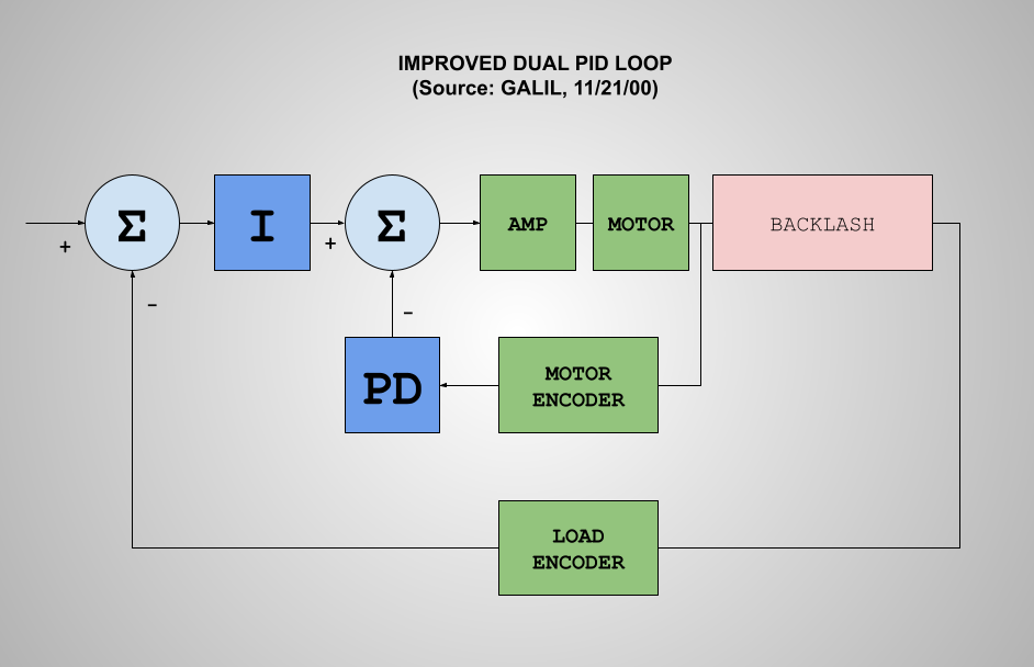
It's been a busy week here, but I'm still working to wrap my head around this. I posted a link earlier to a Galil video about dual loop compensation, and finally had a chance to watch it in detail. It gives a good overview of the approaches and problems. The proposed "improved dual loop" seems to be more or less the same approach that was described rather sparsely in the wiki.
Here's the video again: www.galil.com/learn/online-videos/dual-l...compensation-methods
And my re-drawing of their simplified dual loop.
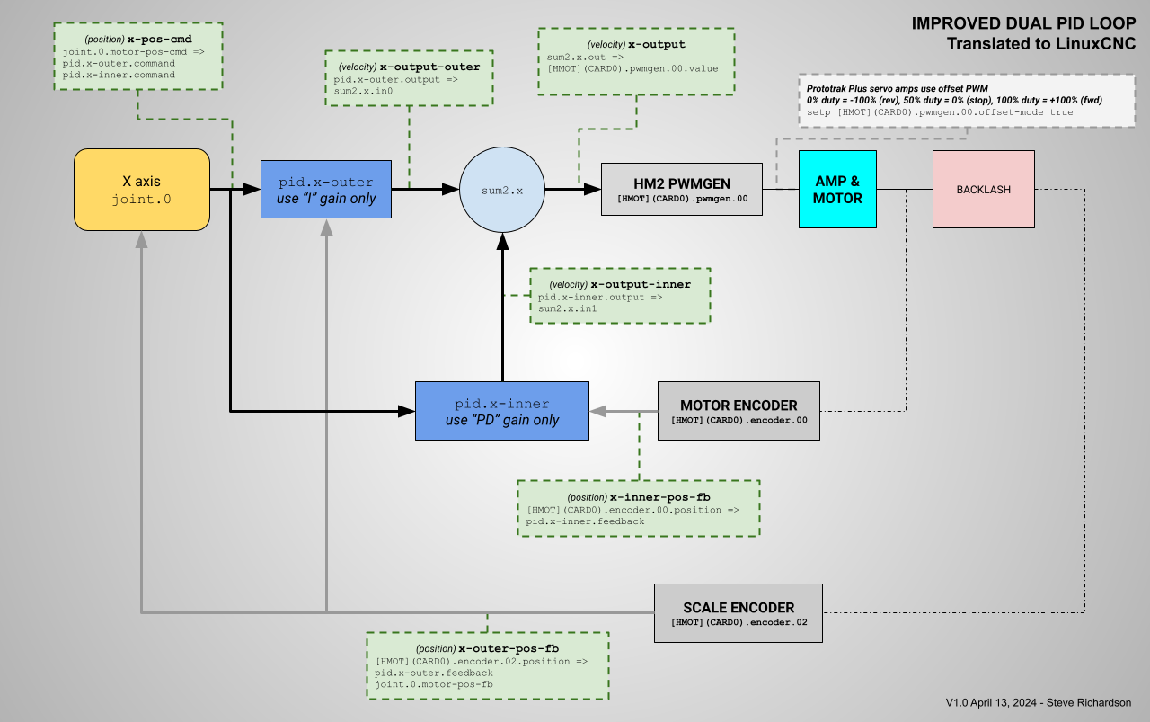
To better my understanding I've been working through the process of translating that simplified loop to show the actual relevant HAL components and signals. Here's my first approach. It's much easier to understand and learn in diagram form than just seeing it as a pile of HAL commands.
I have not yet taken this back down to my shop to rework the config to match the drawing, but hopefully this weekend. Anyone see any glaring mistakes or have other comments?
cheers,
Steve
Here's the video again: www.galil.com/learn/online-videos/dual-l...compensation-methods
And my re-drawing of their simplified dual loop.
To better my understanding I've been working through the process of translating that simplified loop to show the actual relevant HAL components and signals. Here's my first approach. It's much easier to understand and learn in diagram form than just seeing it as a pile of HAL commands.
I have not yet taken this back down to my shop to rework the config to match the drawing, but hopefully this weekend. Anyone see any glaring mistakes or have other comments?
cheers,
Steve
Attachments:
Please Log in or Create an account to join the conversation.
- TangentAudio
- Offline
- Premium Member
-
Less
More
- Posts: 97
- Thank you received: 29
13 Apr 2024 14:37 #298168
by TangentAudio
Replied by TangentAudio on topic Dual PID loops with motor encoder + scale encoder per axis
One thing I'm questioning is whether both the inner and outer PIDs should receive the same position command signal. It isn't really shown explicitly in the simplified Galil drawing, though the wiki example definitely does it this way.
Also, I want to make sure I understand the nomenclature. I think I wrongfully assumed this type of dual loop was a velocity loop (inner) and position loop (outer), but the outputs from both loops are velocities, so I think that's wrong. You can see my confusion in the initial configs I posted as I called the PIDs "vx" and "px".
Next up, the Prototrak DC servo amps are PWM input -> motor output voltage. Varying the voltage on an unloaded DC motor varies its speed (velocity). These are just amps and not closed loop drives - the motor encoder output just comes straight into the Mesa card. I am a bit confused on whether this is called "velocity mode," however. Is that term reserved for a drive which itself runs a loop with the motor encoder to maintain the commanded velocity?
Which leads me to wondering whether the velocity outputs from the motor encoders should be used. Andy, you kind of hinted at that the other day. I'm curious how you would see that fitting into this diagram.
Thanks in advance.
Please Log in or Create an account to join the conversation.
- rodw
-

- Offline
- Platinum Member
-

Less
More
- Posts: 12054
- Thank you received: 4114
13 Apr 2024 15:04 #298172
by rodw
Replied by rodw on topic Dual PID loops with motor encoder + scale encoder per axis
I thought the intention was to close the velocity loop on the drive/amp and to close the position loop from the scales in linuxcnc.
But I've not got any experience to add.
But I've not got any experience to add.
The following user(s) said Thank You: TangentAudio
Please Log in or Create an account to join the conversation.
- TangentAudio
- Offline
- Premium Member
-
Less
More
- Posts: 97
- Thank you received: 29
13 Apr 2024 15:18 #298173
by TangentAudio
Replied by TangentAudio on topic Dual PID loops with motor encoder + scale encoder per axis
Hi Rod,
These 35 year old drives/amps don't have any way to close the loop internally. They're just offset PWM in -> +/- DC voltage out as far as I know. There's no microcontroller in them, and the motor encoders don't connect to them. The signals were passed directly to the primitive Prototrak Plus controller/DRO box.
cheers,
Steve
Please Log in or Create an account to join the conversation.
- Configuring LinuxCNC
- Advanced Configuration
- Dual PID loops with motor encoder + scale encoder per axis
Time to create page: 0.328 seconds