- Configuring LinuxCNC
- Advanced Configuration
- Dual PID loops with motor encoder + scale encoder per axis
Dual PID loops with motor encoder + scale encoder per axis
- rodw
-

- Offline
- Platinum Member
-

- Posts: 11993
- Thank you received: 4084
Please Log in or Create an account to join the conversation.
- TangentAudio
- Offline
- Premium Member
-

- Posts: 97
- Thank you received: 29
Unless I'm missing something, I'm not sure I follow your concern. The switches are located at the end of travel on each end of the table. They stay active for at least 10mm of table travel beyond their initial trigger point. They're positioned as limit switches really, but I should be able to home off of the left one as well.
I know it looks like there's more travel on my Bridgeport table beyond the switches, but it's not actually usable travel. The motor mount interferes with the saddle on the left side which makes a physical limit. On the right side, the bearing casting does clear into the saddle, but this travel isn't really usable as the X axis gage wheel sensor runs off the end of the table, meaning the X axis DRO stops working. The usable travel at each end is essentially where the edge of the table lines up with the edge of the saddle on the respective side, ~24 inches total.
Please Log in or Create an account to join the conversation.
- Tinine
- Offline
- Senior Member
-

- Posts: 42
- Thank you received: 12
Attachments:
Please Log in or Create an account to join the conversation.
- TangentAudio
- Offline
- Premium Member
-
- Posts: 97
- Thank you received: 29
The original motors do not have an analog tacho, but they do have a digital incremental encoder. The drive hardware appears to be an open-loop H bridge that is PWM controlled. The motor encoder does not connect to the drive hardware, but it did connect to the original microcontroller-based control unit.
Other than when stopped, the open loop drive hardware seems to act like a velocity drive. Commanded PWM value correlates to speed, not torque. It is not commanding the drive to output a current, it's commanding the drive to output a voltage.
When stopped with a 0 PWM command, it does appear to be a bit like a torque drive in that the shaft can be rotated (though there is some resistance as you try to spin it quickly).
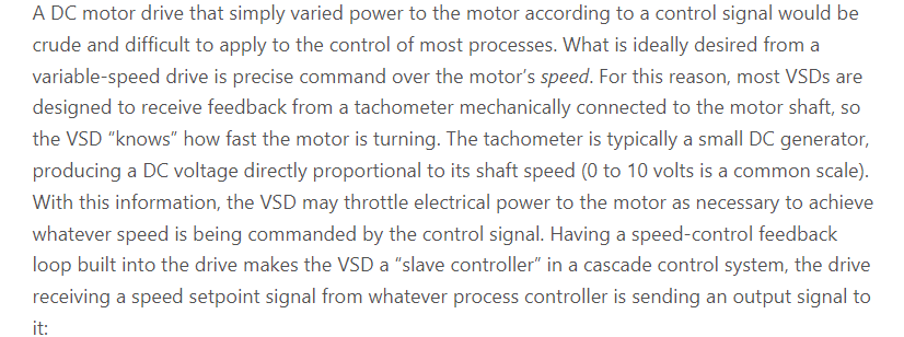
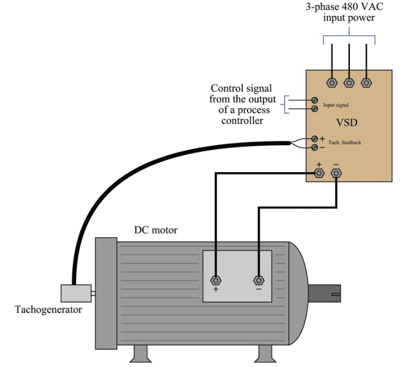
However, in the original system, there was a control loop running on the microcontroller that took take the place of the tacho feedback in your drawing, and if it "saw" motor encoder movement when stopped, it would command a PWM value to try to maintain the zero position. And likewise when moving, it could more closely control the rotational speed to the commanded value by monitoring the encoder in the control loop.
If my understanding is correct, as a system, the original inner loop probably acted like a proper velocity drive, but the feedback was implemented with a digital encoder and a control loop in firmware instead of with analog tachos and op amps. If we focus on just the hardware portion of the drive as we have been, it's really not exactly a velocity drive (but it is similar), nor is it a torque drive (except it kind of looks like one when commanded to stop).
Please Log in or Create an account to join the conversation.
- Tinine
- Offline
- Senior Member
-
- Posts: 42
- Thank you received: 12
The voltage is what produces the current. No voltage - no current.It is not commanding the drive to output a current, it's commanding the drive to output a voltage.
A velocity mode drive rotates the shaft at an RPM that is proportional to the command signal based on the velocity-gain setting.
They are rate devices.
With zero command, the negative-feedback will fight any attempt to rotate the shaft by hand.
If you attempt to drive this motor with only the P-term (I=0,D=0), it will overshoot.
Craig
Please Log in or Create an account to join the conversation.
- TangentAudio
- Offline
- Premium Member
-
- Posts: 97
- Thank you received: 29
Please Log in or Create an account to join the conversation.
- TangentAudio
- Offline
- Premium Member
-
- Posts: 97
- Thank you received: 29
I had some time at lunch today, so I wired up the switches to my temporary control breadboard. The left switch is configured as both X- limit and home, and the "disable limits while homing" option is set in my ini.I don't think your home switch will work. Home switches need to stay triggered until the end of travel. This lets Linuxcnc which direction to travel to find the triggering edge. I predict some big crashes under the current config.
When not homing, both switches act as limits and will e-stop LinuxCNC, which I have tested but did not demo in the video. I have the soft limits set correctly so it stops before tripping the limit when jogging.
cheers,
Steve
Please Log in or Create an account to join the conversation.
- Tinine
- Offline
- Senior Member
-
- Posts: 42
- Thank you received: 12
Craig
Please Log in or Create an account to join the conversation.
- rodw
-
- Offline
- Platinum Member
-
- Posts: 11993
- Thank you received: 4084
Forget useable travel.Hi Rod,
Unless I'm missing something, I'm not sure I follow your concern. The switches are located at the end of travel on each end of the table. They stay active for at least 10mm of table travel beyond their initial trigger point. They're positioned as limit switches really, but I should be able to home off of the left one as well.
For homing, The machine cannot be allowed to be positioned on either side of the home switch and the switch be off in both these positions. It must be set up so it is on on one side and off on the other side of the home trigger point. This lets Linuxcnc know where it is in relation to the home switch. I learnt the hard way.
Please read homing configuration in the docs until you understand this. linuxcnc.org/docs/stable/html/config/ini-homing.html
If using a separate homing switch, it is possible to start homing on the wrong side of the home switch, which combined with HOME_IGNORE_LIMITS option will lead to a hard crash.
Please Log in or Create an account to join the conversation.
- TangentAudio
- Offline
- Premium Member
-
- Posts: 97
- Thank you received: 29
Rod, it is not possible to start homing on the wrong side of the home/limit switch in my setup. The limit switch (left switch) is at the physical limit of where the table can travel due to a mechanical interference between the motor mount and saddle. This is what I mean by usable travel. In the photos I posted, it may look like the table can travel more in the X- direction beyond the switch, but it can't.Forget useable travel.
For homing, The machine cannot be allowed to be positioned on either side of the home switch and the switch be off in both these positions. It must be set up so it is on on one side and off on the other side of the home trigger point. This lets Linuxcnc know where it is in relation to the home switch. I learnt the hard way.
Please read homing configuration in the docs until you understand this. linuxcnc.org/docs/stable/html/config/ini-homing.html
If using a separate homing switch, it is possible to start homing on the wrong side of the home switch, which combined with HOME_IGNORE_LIMITS option will lead to a hard crash.
I really do appreciate the heads up (I'm not immune to dumb mistakes by any means), but just for the record, I have been using LinuxCNC for about 15 years and I'm not a stranger to how it handles homing.
cheers,
Steve
Please Log in or Create an account to join the conversation.
- Configuring LinuxCNC
- Advanced Configuration
- Dual PID loops with motor encoder + scale encoder per axis