- Configuring LinuxCNC
- Advanced Configuration
- Dual PID loops with motor encoder + scale encoder per axis
Dual PID loops with motor encoder + scale encoder per axis
- scotth
- Away
- Elite Member
-

- Posts: 242
- Thank you received: 61
Good luck,
Scott
Please Log in or Create an account to join the conversation.
- TangentAudio
- Offline
- Premium Member
-

- Posts: 97
- Thank you received: 29
The motors do have 2000CPR encoders on them, but they do not tie in with the "dumb" servo amps.
The ballscrews/nuts (or maybe thrust bearings) have some wear and there is more backlash in both X and Y than I'd like to see. When/if I start spending any money to improve things on this machine, that's where it should go first. Maybe I'll luck out and the nuts can be refitted with the next size larger balls and it won't break the bank. I didn't pay that much for the machine, and it's primarily for hobby use, so I don't want it to become a money pit.
Until that time, it doesn't cost anything except my time to play around and see if I can get dual loop working. It's a good learning exercise if nothing else.
Please Log in or Create an account to join the conversation.
- Tinine
- Offline
- Senior Member
-

- Posts: 42
- Thank you received: 12
My experience is that it's better to have PI from the load-mounted encoder.
Dual-loop has always been my standard. Motor shaft angle is unimportant, we care about where the load is. Within reason, backlash becomes a non-issue.
Please Log in or Create an account to join the conversation.
- TangentAudio
- Offline
- Premium Member
-
- Posts: 97
- Thank you received: 29
These are 35 year old dumb servo amps, there's no option to set torque mode on them unfortunately. They take offset PWM in and output +/- DC voltage. The motors have 2000CPR encoders, but they do not connect to the servo amps.
Please Log in or Create an account to join the conversation.
- TangentAudio
- Offline
- Premium Member
-
- Posts: 97
- Thank you received: 29
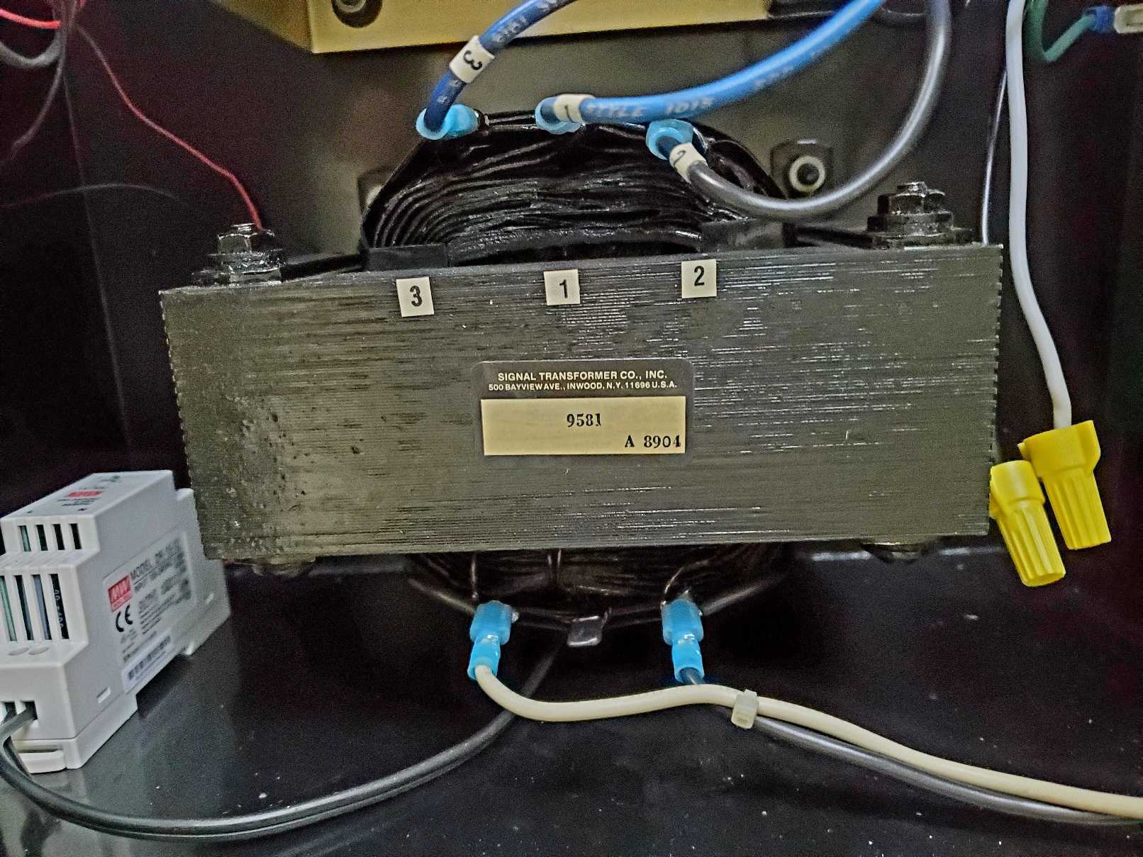
I have not pulled the amp boards from the cage to get photos, but they are pretty primitive. Not much more than a DC power supply really.
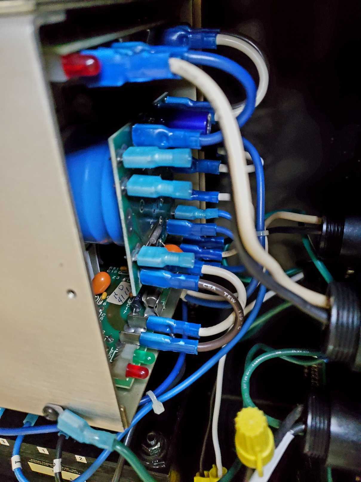
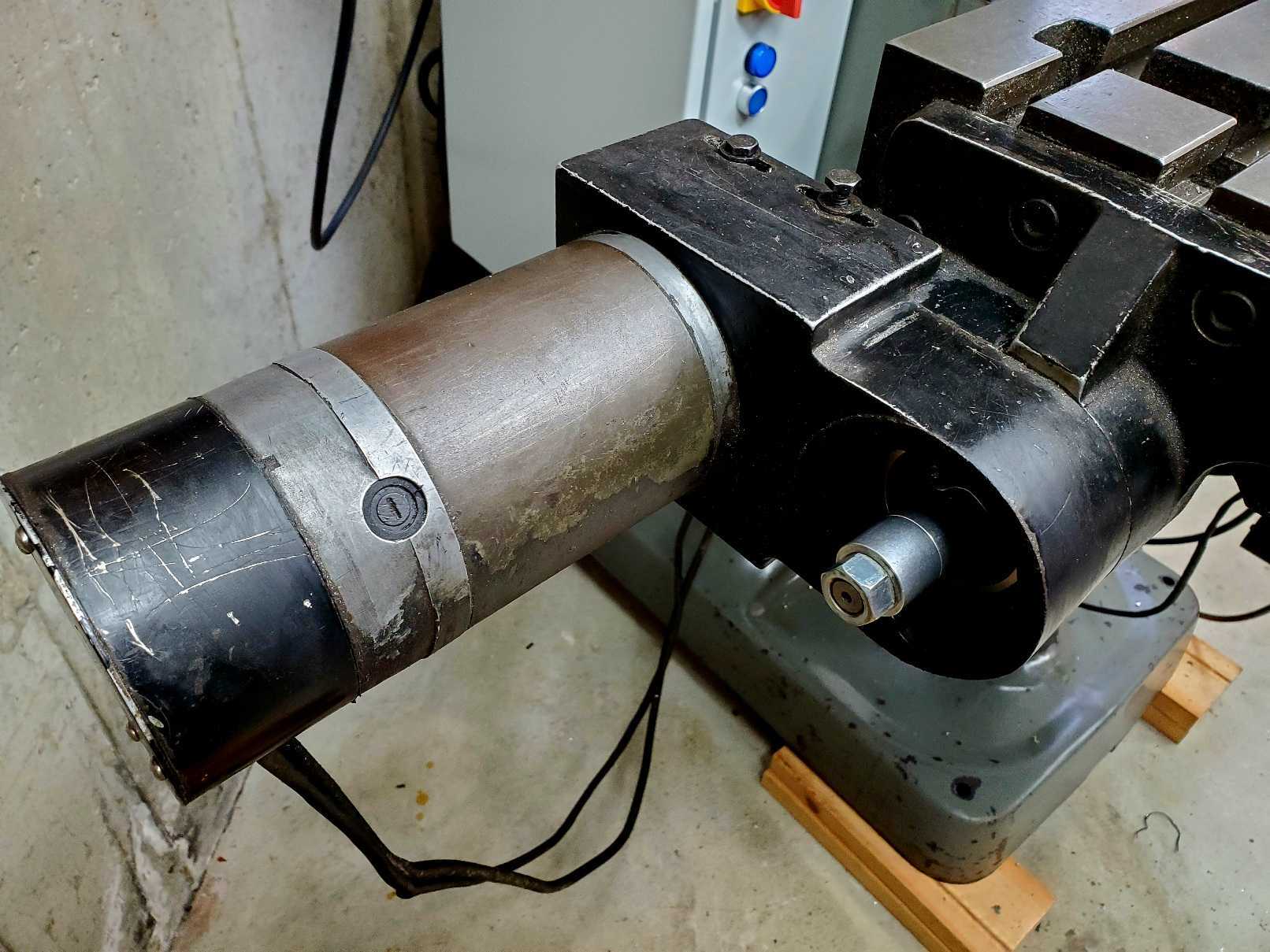
The servo motors are big, brushed DC with a 16T:44T belt drive to couple to 5mm pitch ball screws. The 2000CPR encoder hangs off the back.
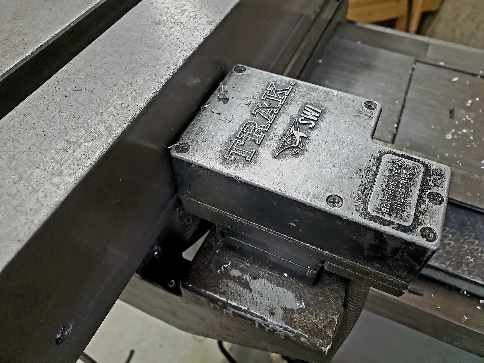
And these are the "infamous" Trak gage wheel table position encoders (on X, Y and the non-motorized quill). They work, kinda, until they get chips in them or they get misaligned.
Attachments:
Please Log in or Create an account to join the conversation.
- Tinine
- Offline
- Senior Member
-
- Posts: 42
- Thank you received: 12
Dumb=good. All you need the amp for is transconductance from a low-level command to a current. Encoder should feed to your controller, not the amp.Tinine,
These are 35 year old dumb servo amps, there's no option to set torque mode on them unfortunately. They take offset PWM in and output +/- DC voltage. The motors have 2000CPR encoders, but they do not connect to the servo amps.
First thing I do with a modern drive is switch it to dumb torque-mode.
Do you have schematics for the drive? Sometimes the conversion is a matter of a solder-jumper.
Please Log in or Create an account to join the conversation.
- TangentAudio
- Offline
- Premium Member
-
- Posts: 97
- Thank you received: 29
I have not stumbled across any schematics yet. The cage with both X and Y amps is Trak part number 15047, but all I can find are listings for a full replacement. I'm not opposed to pulling it apart and doing some reverse engineering, but I haven't gone there just yet.Dumb=good. All you need the amp for is transconductance from a low-level command to a current. Encoder should feed to your controller, not the amp.
First thing I do with a modern drive is switch it to dumb torque-mode.
Do you have schematics for the drive? Sometimes the conversion is a matter of a solder-jumper.
Please Log in or Create an account to join the conversation.
- TangentAudio
- Offline
- Premium Member
-
- Posts: 97
- Thank you received: 29
Without documentation or reverse engineering the board, is there a sort of "black box" bench test I could perform to determine if these amps are actually running in velocity or torque mode? I've got a scope, current probe, DMMs, a programmable DC load, optical tachometer...
Please Log in or Create an account to join the conversation.
- tommylight
-

- Away
- Moderator
-

- Posts: 21764
- Thank you received: 7438
Torque mode = no tacho generator on the motor
Velocity mode = tacho on motor and wired to drive, not wired to control
Position mode = all of those with encoder wired to control
-
Quite a while back i read here somewhere that LinuxCNC can output tacho signal from encoder feedback using some type of DAC converter for drives in velocity mode and using motors without tacho. Not important for this situation.
From the pictures it looks there is no tacho on the motor, so torque mode, and since LinuxCNC can use them with just encoder feedback and a single PID loop, should be easy to make it work, but tuning might be a challenge.
Since you also have linear scales (i hope i am on the right topic), having two loops should be much better, so use motor encoder to close velocity loop in LinuxCNC with the first PID, and use the scales to close the position loop in LinuxCNC with the second PID.
Should be doable, but i have yet to try as i have no linear scales on anything.
Please Log in or Create an account to join the conversation.
- TangentAudio
- Offline
- Premium Member
-
- Posts: 97
- Thank you received: 29
By your logic, these are probably torque mode drives after all? There is a quadrature encoder on the motors, but no tachometer/generator that would produce an analog output relative to velocity. I was conflating tachometers and encoders, since you could use an encoder to infer velocity and it would act as a tacho in theory. That's my lack of servo experience showing.
I might set up a DMM to read voltage across the motor and record voltages as I step through a series of open loop PWM control values across the full scale range. I could do another run and measure current as well. Might be even better to do it with a large load resistor (or a DC load) since that would eliminate the back EMF from the motor influencing the reading?
At least then it should be apparent whether voltage or current is changed proportionally to the control input and I could convince myself what sort of drives I have !

.
Please Log in or Create an account to join the conversation.
- Configuring LinuxCNC
- Advanced Configuration
- Dual PID loops with motor encoder + scale encoder per axis