Home switches wiring / setup
- remon_v
- Offline
- Premium Member
-

- Posts: 97
- Thank you received: 7
I won’t use the word GND anymore… it’s confusing to me.
Still can’t wrap my head around it why it didn’t work…
Please Log in or Create an account to join the conversation.
- Clive S
- Offline
- Platinum Member
-

- Posts: 2204
- Thank you received: 486
While I’m waiting for my new BOB to arrive, I will try to draw up the wiring in the next days.
I won’t use the word GND anymore… it’s confusing to me.
Still can’t wrap my head around it why it didn’t work…
Ok don't use stepconf again as it will overwrite the files. Hand edit.
Also make sure you are actually using the correct hal and ini files that I modded for you.
You can check that by looking at the gui on startup and seeing the joints 0-4 shown. ie not axis X,Y,Z
Don't forget to check the pp cable. You seem to shy away from it.
Good luck
Please Log in or Create an account to join the conversation.
- remon_v
- Offline
- Premium Member
-
- Posts: 97
- Thank you received: 7
Yes, I'm aware I can't use the stepconf anymore, I was hand editing already.
I will use your edited files, I saw you added 'kinstype=BOTH' and I see joint 0-4.
About the PP Checker, I'm not sure what to do... I have an onboard parallel port.
I have to disconnect the cable right?
I can get it to run, and I press all the output pins (the turn green)... but not sure what to do with the input pins. Todd mentioned I can trigger the with a resistor, but I don't have any.
I also couldn't find a tutorial/explanation on how to use it...
Please Log in or Create an account to join the conversation.
- Clive S
- Offline
- Platinum Member
-
- Posts: 2204
- Thank you received: 486
Thanks Clive for the reply!
Yes, I'm aware I can't use the stepconf anymore, I was hand editing already.
I will use your edited files, I saw you added 'kinstype=BOTH' and I see joint 0-4.
About the PP Checker, I'm not sure what to do... I have an onboard parallel port.
I have to disconnect the cable right?
I can get it to run, and I press all the output pins (the turn green)... but not sure what to do with the input pins. Todd mentioned I can trigger the with a resistor, but I don't have any.
I also couldn't find a tutorial/explanation on how to use it...
Ok I have loaded the PPort checker the pport cable has to be connected to the PC and the bob.
To check the inputs bob needs to BOB powered with 12-24v and 5v on the BOB I have re inputs just use a bit of wire and short pin 10 to -ve (gnd) last pin. do the same with 11,12,13,15. The leds should change colour.
You still have not answered the cable continuity Q. !!
Please Log in or Create an account to join the conversation.
- remon_v
- Offline
- Premium Member
-
- Posts: 97
- Thank you received: 7
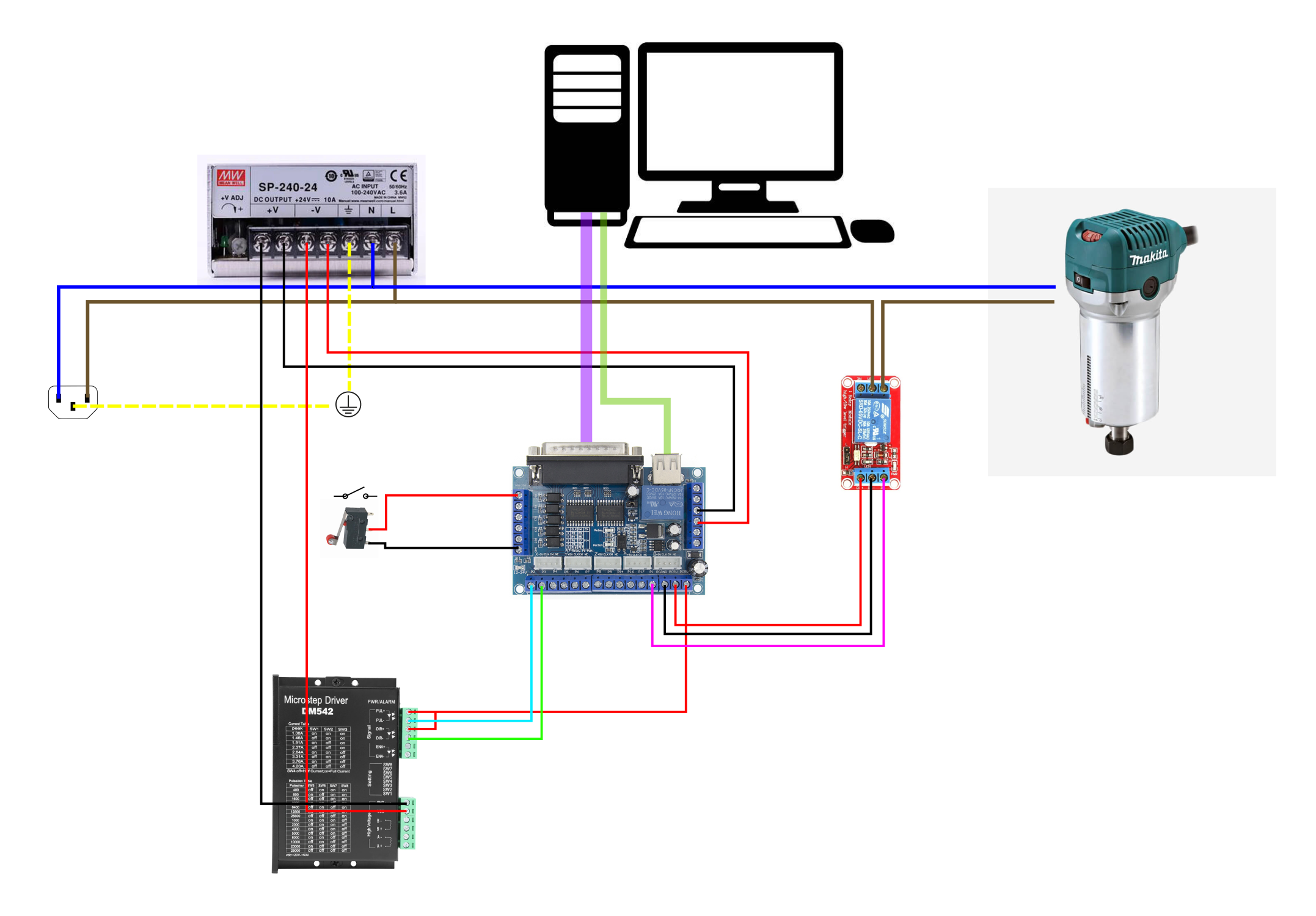
p.s. this is how I had set it up, but I will swap out the USB connection by your way and connect it to a 5V power supply.
p.s.2 Between power in and the 24V power supply, there's an on/off switch, E-stop, circuit breaker and contactor. But I didn't drew does yet.
I'll check the PP tester when my BOB arrives, I can't check it now.
About the cable continuity.. if I do the PP tester, it will confirm the cable continuity aswell right? Or am I wrong here?
Attachments:
Please Log in or Create an account to join the conversation.
- Clive S
- Offline
- Platinum Member
-
- Posts: 2204
- Thank you received: 486
Re the cable I don't know why you are being stubborn with checking it. Its only a 2 minute job and it takes it out of the equation.

Please Log in or Create an account to join the conversation.
- remon_v
- Offline
- Premium Member
-
- Posts: 97
- Thank you received: 7
While you where replying.. I was checking it already

Please Log in or Create an account to join the conversation.
- Clive S
- Offline
- Platinum Member
-
- Posts: 2204
- Thank you received: 486
At lastremon_v post=234924 userid=31275I have just checked the cable, all the pins have continuity! I just had to think of a way how to check it... but I've managed it.

Please Log in or Create an account to join the conversation.
- remon_v
- Offline
- Premium Member
-
- Posts: 97
- Thank you received: 7
Yes I will do that... the rest seems fine?Remove the usb connection and connect the 5V ps to the red/black wires where your little relay board is connected.
I still can't get my head around it why it' didn't work... especially now I've checked the cable...
Please Log in or Create an account to join the conversation.
- Clive S
- Offline
- Platinum Member
-
- Posts: 2204
- Thank you received: 486
Remove the usb connection and connect the 5V ps to the red/black wires where your little relay board is connected.
Yes I will do that... the rest seems fine?
I still can't get my head around it why it' didn't work... especially now I've checked the cable...
It could be that just the usb connection was not supplying enough power
Please Log in or Create an account to join the conversation.