Remora - ethernet NVEM cnc board
06 Apr 2022 15:43 #239449
by Domi
Replied by Domi on topic Remora - ethernet NVEM cnc board
So far, I only use remora-eth.hal
Please Log in or Create an account to join the conversation.
06 Apr 2022 23:43 #239480
by cakeslob
Replied by cakeslob on topic Remora - ethernet NVEM cnc board
ok domi, for simplicity, lets just use remora-eth.hal
I dont have a nvem board but Ill see what I can do, so I am learning this along side you. I dont know if there was a docs I missed for this board specifically, and Im also not very good with hal.
First, lets see what/where the inputs are. google image of the board and a quick check of the firmware shows the inputs are numbered starting from STOP
" Module* PROBE = new DigitalPin(*ptrInputs, 0, "PD_9", 1,"
Ok, so "Module* PROBE" is probably the name on the board , and Im pretty sure the number to the right is the remora input pin number "1"
so in hal, the PROBE port is hal pin remora.input.1, now we need to connect them within/to linuxcnc so linuxcnc knows what goes where.
linuxcnc.org/docs/devel/html/hal/intro.html
remora-docs.readthedocs.io/en/latest/sof...dstops-home-switches
linuxcnc.org/docs/devel/html/man/man9/mo....9.html#JOINT%20PINS
linuxcnc.org/docs/devel/html/man/man9/mo...9.html#MOTION%20PINS
We know now which pin is where on the board, now to connect them to linuxcnc, using the examples from above, and if probe is remora.input1, we then connect it to linuxcnc pin motion.probe-input, and we do the same for limits. im pretty sure this is safe, so add it to your remora eth.hal and see what happens
Check out some more of the configuration and hal section of the docs, because if you understand some of the basic concepts, it will make this next set of instructions easier
linuxcnc.org/docs/
I dont have a nvem board but Ill see what I can do, so I am learning this along side you. I dont know if there was a docs I missed for this board specifically, and Im also not very good with hal.
First, lets see what/where the inputs are. google image of the board and a quick check of the firmware shows the inputs are numbered starting from STOP
// INPUTS
    Module* STOP = new DigitalPin(*ptrInputs, 0, "PD_8", 0, true, NONE);
    servoThread->registerModule(STOP);

    Module* PROBE = new DigitalPin(*ptrInputs, 0, "PD_9", 1, true, NONE);
    servoThread->registerModule(PROBE);

    Module* INP3 = new DigitalPin(*ptrInputs, 0, "PD_10", 2, true, NONE);
    servoThread->registerModule(INP3);

    Module* INP4 = new DigitalPin(*ptrInputs, 0, "PD_11", 3, true, NONE);
    servoThread->registerModule(INP4);

    Module* INP5 = new DigitalPin(*ptrInputs, 0, "PD_14", 4, true, NONE);
    servoThread->registerModule(INP5);

    Module* INP6 = new DigitalPin(*ptrInputs, 0, "PD_15", 5, true, NONE);
    servoThread->registerModule(INP6);

    Module* INP7 = new DigitalPin(*ptrInputs, 0, "PC_6", 6, true, NONE);
    servoThread->registerModule(INP7);

    Module* INP8 = new DigitalPin(*ptrInputs, 0, "PC_7", 7, true, NONE);
    servoThread->registerModule(INP8);

    Module* INP9 = new DigitalPin(*ptrInputs, 0, "PC_8", 8, true, NONE);
    servoThread->registerModule(INP9);

    Module* INP10 = new DigitalPin(*ptrInputs, 0, "PC_9", 9, true, NONE);
    servoThread->registerModule(INP10);

    Module* INP11 = new DigitalPin(*ptrInputs, 0, "PA_11", 10, true, NONE);
    servoThread->registerModule(INP11);

    Module* INP12 = new DigitalPin(*ptrInputs, 0, "PA_12", 11, true, NONE);
    servoThread->registerModule(INP12);

    Module* SRO = new DigitalPin(*ptrInputs, 0, "PB_14", 12, true, NONE);
    servoThread->registerModule(SRO);

    Module* SJR = new DigitalPin(*ptrInputs, 0, "PB_15", 13, true, NONE);
    servoThread->registerModule(SJR);

    Module* x100 = new DigitalPin(*ptrInputs, 0, "PA_15", 14, true, NONE);
    servoThread->registerModule(x100);

    Module* x10 = new DigitalPin(*ptrInputs, 0, "PC_10", 15, true, NONE);
    servoThread->registerModule(x10);

    Module* x1 = new DigitalPin(*ptrInputs, 0, "PC_11", 16, true, NONE);
    servoThread->registerModule(x1);

    Module* ESTOP = new DigitalPin(*ptrInputs, 0, "PC_12", 17, true, NONE);
    servoThread->registerModule(ESTOP);

    Module* Xin = new DigitalPin(*ptrInputs, 0, "PD_7", 18, true, NONE);
    servoThread->registerModule(Xin);

    Module* Yin = new DigitalPin(*ptrInputs, 0, "PD_4", 19, true, NONE);
    servoThread->registerModule(Yin);

    Module* Zin = new DigitalPin(*ptrInputs, 0, "PD_3", 20, true, NONE);
    servoThread->registerModule(Zin);

    Module* Ain = new DigitalPin(*ptrInputs, 0, "PD_2", 21, true, NONE);
    servoThread->registerModule(Ain);

    Module* Bin = new DigitalPin(*ptrInputs, 0, "PD_1", 22, true, NONE);
    servoThread->registerModule(Bin);

    Module* Cin = new DigitalPin(*ptrInputs, 0, "PD_0", 23, true, NONE);
    servoThread->registerModule(Cin);

    Module* WHA = new DigitalPin(*ptrInputs, 0, "PB_7", 24, false, NONE);
    servoThread->registerModule(WHA);

    Module* WHB = new DigitalPin(*ptrInputs, 0, "PB_6", 25, false, NONE);
    servoThread->registerModule(WHB);

    Module* INDEX = new DigitalPin(*ptrInputs, 0, "PC_15", 25, false, NONE);
    servoThread->registerModule(INDEX);
" Module* PROBE = new DigitalPin(*ptrInputs, 0, "PD_9", 1,"
Ok, so "Module* PROBE" is probably the name on the board , and Im pretty sure the number to the right is the remora input pin number "1"
so in hal, the PROBE port is hal pin remora.input.1, now we need to connect them within/to linuxcnc so linuxcnc knows what goes where.
linuxcnc.org/docs/devel/html/hal/intro.html
remora-docs.readthedocs.io/en/latest/sof...dstops-home-switches
linuxcnc.org/docs/devel/html/man/man9/mo....9.html#JOINT%20PINS
linuxcnc.org/docs/devel/html/man/man9/mo...9.html#MOTION%20PINS
We know now which pin is where on the board, now to connect them to linuxcnc, using the examples from above, and if probe is remora.input1, we then connect it to linuxcnc pin motion.probe-input, and we do the same for limits. im pretty sure this is safe, so add it to your remora eth.hal and see what happens
net Probe-IN    remora.input.1  => motion.probe-input
net X-min       remora.input.2  => joint.0.home-sw-in joint.0.neg-lim-sw-in
net Y-min       remora.input.3  => joint.1.home-sw-in joint.1.neg-lim-sw-in
net Z-min       remora.input.4  => joint.2.home-sw-in joint.2.neg-lim-sw-in
Check out some more of the configuration and hal section of the docs, because if you understand some of the basic concepts, it will make this next set of instructions easier
linuxcnc.org/docs/
The following user(s) said Thank You: Domi
Please Log in or Create an account to join the conversation.
07 Apr 2022 00:09 #239483
by cakeslob
Replied by cakeslob on topic Remora - ethernet NVEM cnc board
If you are following along with the previous post and are understanding some of the basics of hal and what it is, we can streamline your configuration process by using the stepconf. stepconf is used for making easy parallel port configurations. Different hardware, but the core concepts are the same, being we need to link hardware pins to software pins
linuxcnc.org/docs/stable/html/config/stepconf.html
If you generate a file for the parallel port, you can open up the hal file it created, and use that as reference. for exampleyou would replace the hal pin for parport, with the pin for remora hal. and would become this.
This is all probably more involved than you were expecting, but remora for nvem is pretty new
linuxcnc.org/docs/stable/html/config/stepconf.html
If you generate a file for the parallel port, you can open up the hal file it created, and use that as reference. for example
net X-neg-limit parport.0.pin-11-in => joint.0.neg-lim-sw-innet X-neg-limit remora.input.2 => joint.0.neg-lim-sw-inThis is all probably more involved than you were expecting, but remora for nvem is pretty new
The following user(s) said Thank You: Domi
Please Log in or Create an account to join the conversation.

08 Apr 2022 03:42 - 08 Apr 2022 03:44 #239615
by scotta
Replied by scotta on topic Remora - ethernet NVEM cnc board
Thanks cakeslob for helping out. I've started on an "example" 3 axis config which hopefully get people going quicker. As we add functionality I'll update the example.
I've remapped the IO and updated the bin file in the repo. The reason for remapping is to align with the physical layout of the controller.
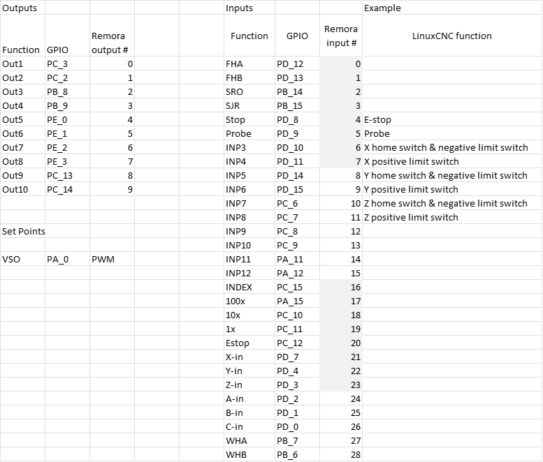
The example has been aligned to this IO mapping: github.com/scottalford75/Remora/tree/fea...igSamples/remora-eth
I've remapped the IO and updated the bin file in the repo. The reason for remapping is to align with the physical layout of the controller.
The example has been aligned to this IO mapping: github.com/scottalford75/Remora/tree/fea...igSamples/remora-eth
Attachments:
Last edit: 08 Apr 2022 03:44 by scotta.
Please Log in or Create an account to join the conversation.
09 Apr 2022 07:01 #239714
by Domi
Replied by Domi on topic Remora - ethernet NVEM cnc board
Hi cakeslob: I tried the limit switches according to my instructions. I see them but it shows them on and when I attach the metal so off. All input pins on NVEM are FALSE without connection. I read and tried a lot. But I can't reverse it. I use PNP NC and it looks like the signal is the opposite. I exchanged arrows. He tried data in and out and other different things according to the instructions. I also read the forum but nothing helped. Won't it be that NVEM has Unconnected pins like FALSE? I also tried to use the procedure for realtime but without point. Well thank you.
Please Log in or Create an account to join the conversation.
09 Apr 2022 08:15 #239715
by Domi
Replied by Domi on topic Remora - ethernet NVEM cnc board
Attachments:
Please Log in or Create an account to join the conversation.
09 Apr 2022 12:22 #239729
by Domi
Replied by Domi on topic Remora - ethernet NVEM cnc board
scotta: now I have to download the file Remora-NVEM bin to NVEM again via STlink? Or some other files? And where to place the modified remora-eth file? Or will I use only hal and others from the remora-eth file? and what to do with the file py? Well thank you
Please Log in or Create an account to join the conversation.
09 Apr 2022 16:13 #239747
by cakeslob
Replied by cakeslob on topic Remora - ethernet NVEM cnc board
Ok, thats good domi, if you can see the pins changing state that is progress. If you want to use the new sample config posted by scott, you will need to load the new firmware bin file to the nvem with st link like you did before. the new firmware changes the pin layout , so the new firmware matches the new hal. With the new firmware, you need to change the remo-eth.hal, but to keep things simple , just download the whole folder and keep them both in separate config folders.
The upload config .py file is something new that I am excited for, dont know how it works yet.
Back to the limit switch. if your limit switches change state, that is good. Now we just need to invert the state. Try adding this to the hal part
The upload config .py file is something new that I am excited for, dont know how it works yet.
Back to the limit switch. if your limit switches change state, that is good. Now we just need to invert the state. Try adding this to the hal part
net X-neg-limit remora.input.2 => joint.0.neg-lim-sw-in-notPlease Log in or Create an account to join the conversation.
09 Apr 2022 16:57 #239752
by Domi
Replied by Domi on topic Remora - ethernet NVEM cnc board
I've tried that before : does not exist
Please Log in or Create an account to join the conversation.
09 Apr 2022 21:23 - 09 Apr 2022 21:26 #239774
by Domi
Replied by Domi on topic Remora - ethernet NVEM cnc board
So I run the new firmware bin and hal. I didn't move on. Sensors do the same.I can't turn their signal to true / false
Last edit: 09 Apr 2022 21:26 by Domi.
Please Log in or Create an account to join the conversation.
Time to create page: 0.476 seconds