Remora - ethernet NVEM / EC300 / EC500 cnc board
- TimGow
- Offline
- Junior Member
-

Less
More
- Posts: 36
- Thank you received: 3
02 Mar 2024 18:18 - 02 Mar 2024 18:26 #294927
by TimGow
Replied by TimGow on topic Remora - ethernet NVEM / EC300 / EC500 cnc board
The dir signal is most likely high for one direction and low for another
Hi cakeslob,
Thank you for your time.
I have bought a low-cost logic analyser with fx2lafw firmware and I hope to utilise the open source sigrok software with ‘Stepper motor’ protocol decoder, to verify my EC300 step/dir timing and rising/falling sense.
It will be interesting to verify the timing that was set in the config.txt.
I haven't managed to get any results using the logic analyser; I will keep trying.
I still have inconsistent steps using the LCNC jog 1mm 5mm etc presets, so I tried assessing the EC300 step output signal using an oscilloscope. I have little experience using this secondhand oscilloscope so please jump in with advice on better settings.
First, I verified that the driver and stepper motor are working properly, independent of the EC300. The HBS860H driver has a PC program to adjust parameters and test run the stepper.
youtube.com/shorts/UL64FQ7sgdE
These are my oscilloscope results, using two channels, CH1 (yellow trace) on 'XP+', CH2 (blue trace) on 'XP-' and the ground from both probes on 'SYSTEM GND'.
Please advise of better oscilloscope connection to prove out step pulses. Maybe I should attach probe grounds to 'COM-' adjacent to 'IN01'?
youtube.com/shorts/qvkYAdwXUSY
youtube.com/shorts/Cg28S9qeHRg
I'm looking for the best means of verifying the step pulses, has anyone else done this?
Last edit: 02 Mar 2024 18:26 by TimGow.
Please Log in or Create an account to join the conversation.
- cakeslob
- Offline
- Platinum Member
-

Less
More
- Posts: 926
- Thank you received: 278
02 Mar 2024 21:21 #294950
by cakeslob
Replied by cakeslob on topic Remora - ethernet NVEM / EC300 / EC500 cnc board
tim, ill be honest, all this numbers stuff is over my head.
you can verify the output from the ec300 (software side) using halscope
linuxcnc.org/docs/stable/html/hal/tools.html#sec:halscope
you can verify the output from the ec300 (software side) using halscope
linuxcnc.org/docs/stable/html/hal/tools.html#sec:halscope
Please Log in or Create an account to join the conversation.
- scotta
-
 Topic Author
- Offline
- Platinum Member
-
Less
More
- Posts: 959
- Thank you received: 489
03 Mar 2024 00:23 #294965
by scotta
Replied by scotta on topic Remora - ethernet NVEM / EC300 / EC500 cnc board
Hi Tim,
I use a cheap logic analysier for my development work. That's how I've tested the step timing capabilities of the firmware. The traces below are from the EC300 / EC500 looking an only one side of the differential driver. What you are seeing on your scope is the two sides of the differential driver doing their thing.
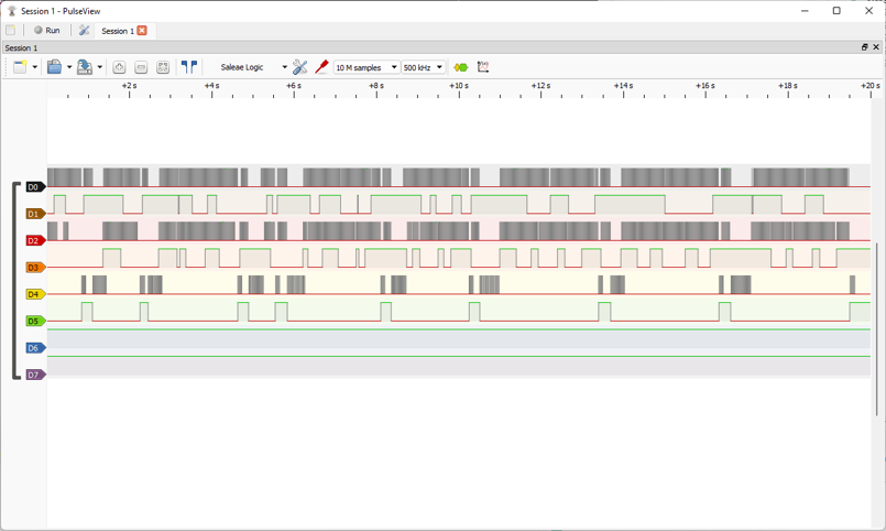
I use a cheap logic analysier for my development work. That's how I've tested the step timing capabilities of the firmware. The traces below are from the EC300 / EC500 looking an only one side of the differential driver. What you are seeing on your scope is the two sides of the differential driver doing their thing.
Attachments:
The following user(s) said Thank You: tommylight, TimGow
Please Log in or Create an account to join the conversation.
- Meichinger
- Offline
- New Member
-

Less
More
- Posts: 6
- Thank you received: 1
03 Mar 2024 09:55 #294998
by Meichinger
Replied by Meichinger on topic Remora - ethernet NVEM / EC300 / EC500 cnc board
Hi LinuxCNC forum and scotta,
Thank you for all of your work!
I am currently trying to flash remora rt1052-3.1.3.bin onto an NVEM V5. Unfortunately without success.
what I have done so far:
1) bought two ST Link V2 and flashed CMSIS DAP. -> worked without an issue.
2)results in:
# Probe/Board Unique ID Target
0 X893 ARM CMSIS-DAP 0001A0000000 n/a
3)gives me:
C Unexpected ACK value (0) returned by probe [__main__]
The NVEM board is powerd on (24V) and three red LEDs light up.
After flashing the ST Link V2, I accidentally flipped the cover so that I connected 5V to CLK and 3.3 to DIO. Could this be the reason? Did I destroy the RT1052 by applying 5V to the CLK pin?
Thank you!
Michael
Thank you for all of your work!
I am currently trying to flash remora rt1052-3.1.3.bin onto an NVEM V5. Unfortunately without success.
what I have done so far:
1) bought two ST Link V2 and flashed CMSIS DAP. -> worked without an issue.
2)
sudo pyocd list # Probe/Board Unique ID Target
0 X893 ARM CMSIS-DAP 0001A0000000 n/a
3)
sudo pyocd flash ./remora-rt1052-3.1.2.bin --target mimxrt1050_quadspi --connect=under-resetC Unexpected ACK value (0) returned by probe [__main__]
The NVEM board is powerd on (24V) and three red LEDs light up.
After flashing the ST Link V2, I accidentally flipped the cover so that I connected 5V to CLK and 3.3 to DIO. Could this be the reason? Did I destroy the RT1052 by applying 5V to the CLK pin?
Thank you!
Michael
Please Log in or Create an account to join the conversation.
- vpomerleau
- Away
- Junior Member
-
Less
More
- Posts: 27
- Thank you received: 3
03 Mar 2024 11:13 - 05 Mar 2024 10:43 #295005
by vpomerleau
Replied by vpomerleau on topic Remora - ethernet NVEM / EC300 / EC500 cnc board
Hi Scott, thank you for the reply about the missing pins in the EC500 config. So this morning I decided to play with my config file and short some pins together, here are all the missing pins for the EC500. I have one question for you, do you think the missing pins may be the reason why my NVMPG is not displaying the data correctly ?
{
"Thread": "Servo",
"Type": "Digital Pin",
"Comment": "TX/BIN",
"Pin": "P4_26",
"Mode": "Input",
"Data Bit": 22,
"Invert": "True"
},
{
"Thread": "Servo",
"Type": "Digital Pin",
"Comment": "RX/CIN",
"Pin": "P4_23",
"Mode": "Input",
"Data Bit": 23,
"Invert": "True"
},
{
"Thread": "Servo",
"Type": "Digital Pin",
"Comment": "XIN",
"Pin": "P4_22",
"Mode": "Input",
"Data Bit": 24,
"Invert": "True"
},
{
"Thread": "Servo",
"Type": "Digital Pin",
"Comment": "YIN",
"Pin": "P4_21",
"Mode": "Input",
"Data Bit": 25,
"Invert": "True"
},
{
"Thread": "Servo",
"Type": "Digital Pin",
"Comment": "ZIN",
"Pin": "P4_20",
"Mode": "Input",
"Data Bit": 26,
"Invert": "True"
},
{
"Thread": "Servo",
"Type": "Digital Pin",
"Comment": "AIN",
"Pin": "P4_19",
"Mode": "Input",
"Data Bit": 27,
"Invert": "True"
},
{
"Thread": "Servo",
"Type": "Digital Pin",
"Comment": "X100IN",
"Pin": "P4_18",
"Mode": "Input",
"Data Bit": 28,
"Invert": "True"
},
{
"Thread": "Servo",
"Type": "Digital Pin",
"Comment": "X10IN",
"Pin": "P4_17",
"Mode": "Input",
"Data Bit": 29,
"Invert": "True"
},
{
"Thread": "Servo",
"Type": "Digital Pin",
"Comment": "EP",
"Pin": "P4_16",
"Mode": "Input",
"Data Bit": 30,
"Invert": "True"
},
{
"Thread": "Servo",
"Type": "Digital Pin",
"Comment": "INDEX",
"Pin": "P3_27",
"Mode": "Input",
"Data Bit": 31,
"Invert": "True"
},
{
"Thread": "Servo",
"Type": "Digital Pin",
"Comment": "TX/BIN",
"Pin": "P4_26",
"Mode": "Input",
"Data Bit": 22,
"Invert": "True"
},
{
"Thread": "Servo",
"Type": "Digital Pin",
"Comment": "RX/CIN",
"Pin": "P4_23",
"Mode": "Input",
"Data Bit": 23,
"Invert": "True"
},
{
"Thread": "Servo",
"Type": "Digital Pin",
"Comment": "XIN",
"Pin": "P4_22",
"Mode": "Input",
"Data Bit": 24,
"Invert": "True"
},
{
"Thread": "Servo",
"Type": "Digital Pin",
"Comment": "YIN",
"Pin": "P4_21",
"Mode": "Input",
"Data Bit": 25,
"Invert": "True"
},
{
"Thread": "Servo",
"Type": "Digital Pin",
"Comment": "ZIN",
"Pin": "P4_20",
"Mode": "Input",
"Data Bit": 26,
"Invert": "True"
},
{
"Thread": "Servo",
"Type": "Digital Pin",
"Comment": "AIN",
"Pin": "P4_19",
"Mode": "Input",
"Data Bit": 27,
"Invert": "True"
},
{
"Thread": "Servo",
"Type": "Digital Pin",
"Comment": "X100IN",
"Pin": "P4_18",
"Mode": "Input",
"Data Bit": 28,
"Invert": "True"
},
{
"Thread": "Servo",
"Type": "Digital Pin",
"Comment": "X10IN",
"Pin": "P4_17",
"Mode": "Input",
"Data Bit": 29,
"Invert": "True"
},
{
"Thread": "Servo",
"Type": "Digital Pin",
"Comment": "EP",
"Pin": "P4_16",
"Mode": "Input",
"Data Bit": 30,
"Invert": "True"
},
{
"Thread": "Servo",
"Type": "Digital Pin",
"Comment": "INDEX",
"Pin": "P3_27",
"Mode": "Input",
"Data Bit": 31,
"Invert": "True"
},
Last edit: 05 Mar 2024 10:43 by vpomerleau.
The following user(s) said Thank You: Cold Turkey, cnc-phil
Please Log in or Create an account to join the conversation.
- Cold Turkey
- Offline
- Senior Member
-

Less
More
- Posts: 49
- Thank you received: 14
04 Mar 2024 00:31 - 04 Mar 2024 06:42 #295102
by Cold Turkey
Replied by Cold Turkey on topic Remora - ethernet NVEM / EC300 / EC500 cnc board
@vpomerleau
Mate I asked you directly about this and you said you had all the inputs working? Since the NVMPG uses the RX and TX pins on the mpg port I'd say you probably need these going at a minimum. Don't have one to test sorry. I also have two different versions of the EC500 user manual, one of which states that it can use the NVMPG and another that says it can not.
(edit) I still only have pins 6,7,8and 15 working on the mpg. Thought I had more but had made a mistake due to poor wiring and no sleep.
Just ran one machine at 6000mm a min with a scale of 5000") Scott is a legend.
Scott is a legend.
I'm also finishing up a full start to finish guide using the current linuxcnc 2.9 install to flash the ec500. I've been testing as many debug probes as I can my hands on and so far I have them all working. Hopefully we can post it to the remora docs if it's considered good enough.
Mate I asked you directly about this and you said you had all the inputs working? Since the NVMPG uses the RX and TX pins on the mpg port I'd say you probably need these going at a minimum. Don't have one to test sorry. I also have two different versions of the EC500 user manual, one of which states that it can use the NVMPG and another that says it can not.
(edit) I still only have pins 6,7,8and 15 working on the mpg. Thought I had more but had made a mistake due to poor wiring and no sleep.
Just ran one machine at 6000mm a min with a scale of 5000
Scott is a legend.I'm also finishing up a full start to finish guide using the current linuxcnc 2.9 install to flash the ec500. I've been testing as many debug probes as I can my hands on and so far I have them all working. Hopefully we can post it to the remora docs if it's considered good enough.
Attachments:
Last edit: 04 Mar 2024 06:42 by Cold Turkey. Reason: Tested again - hardware gave false positive.
Please Log in or Create an account to join the conversation.
- vpomerleau
- Away
- Junior Member
-
Less
More
- Posts: 27
- Thank you received: 3
04 Mar 2024 00:52 - 04 Mar 2024 00:54 #295103
by vpomerleau
Replied by vpomerleau on topic Remora - ethernet NVEM / EC300 / EC500 cnc board
Hi Cold Turkey
Yes the NVMPG is working on my RT1052, it just the display that doesn't update, nothing change on the display but the machine move with the wheel and the axis change. On my STM32, the display update normally. Before today, I didn't had the input pin set my config file and it was working. I think you have to set the mpg pin in config only for the standard model. If I understand correctly, the NVMPG communicate only via serial protocol and on my system, it seem to only work on one side. the EC500 receive the commands but NVMPG doesn't receive the updated display data from the controller. I just posted the pins numbers for anyone who need them! Funny that 2 manual say something different but it work fine on my V2 stm version.Thank you for your help
Yes the NVMPG is working on my RT1052, it just the display that doesn't update, nothing change on the display but the machine move with the wheel and the axis change. On my STM32, the display update normally. Before today, I didn't had the input pin set my config file and it was working. I think you have to set the mpg pin in config only for the standard model. If I understand correctly, the NVMPG communicate only via serial protocol and on my system, it seem to only work on one side. the EC500 receive the commands but NVMPG doesn't receive the updated display data from the controller. I just posted the pins numbers for anyone who need them! Funny that 2 manual say something different but it work fine on my V2 stm version.Thank you for your help
Last edit: 04 Mar 2024 00:54 by vpomerleau.
Please Log in or Create an account to join the conversation.
- TimGow
- Offline
- Junior Member
-
Less
More
- Posts: 36
- Thank you received: 3
04 Mar 2024 08:44 #295116
by TimGow
Replied by TimGow on topic Remora - ethernet NVEM / EC300 / EC500 cnc board
Scott, thank you for the logic analyser output example.
The combination of EC300 and the HBS860H stepper driver is behaving badly for me. The EC300 controls TC6600 drivers just fine for some test NEMA17s.
I'm concerned that the step low and high states are not perhaps within required range (low -0.5 to 1.5V, high 3.5 to 5.0V ?).
Some stepper drivers are fed 5V on step+ and dir+, and the step -'ve and dir -'ve sink to ground when signal is low. I'm wondering what other tests to try.
Please Log in or Create an account to join the conversation.
- Cold Turkey
- Offline
- Senior Member
-
Less
More
- Posts: 49
- Thank you received: 14
04 Mar 2024 22:51 #295168
by Cold Turkey
Replied by Cold Turkey on topic Remora - ethernet NVEM / EC300 / EC500 cnc board
@ Meichinger
Mate I was playing around with boards last night and ran into exactly the same problem.
Strangest thing, I flashed the firmware to the EC500 using a modified ST-Link and then I tried to do it again a few minutes later using the exact same hardware and got that problem. I then plugged in another EC500 and the problem was still there.
I shut everything down and then tried again this morning with the exact same hardware. It worked once and then when I connected another EC500 I got that error again.
I switched to an unmodified ST-Link and it works every time no problem.
I would say you have a dodgy ST-Link. You can test this by unplugging the cables from the ST-Link to the EC500 but leave the ST-Link connected to the computer. You should get a different error message to what you are getting.
Sorry I can't help further with that.
Please Log in or Create an account to join the conversation.
- Cold Turkey
- Offline
- Senior Member
-
Less
More
- Posts: 49
- Thank you received: 14
04 Mar 2024 23:10 #295169
by Cold Turkey
Replied by Cold Turkey on topic Remora - ethernet NVEM / EC300 / EC500 cnc board
@vpomerleau
Can you please confirm if the config you have uploaded is for the STM32 EC500 or the RT1052 EC500?
Can you please confirm if the config you have uploaded is for the STM32 EC500 or the RT1052 EC500?
Please Log in or Create an account to join the conversation.
Time to create page: 0.386 seconds