[ Vfdmod ] An easy VFD control over MODBUS RTU
- bbsr_5a
- Offline
- Platinum Member
-

Less
More
- Posts: 544
- Thank you received: 106
08 Jun 2020 06:58 #170587
by bbsr_5a
Replied by bbsr_5a on topic [ Vfdmod ] An easy VFD control over MODBUS RTU
starting to have 2 comps of the same workaround is quite challenging the helping people here
as most use the system internal mb2hal comp and now this jups in on a deb install only view are using")
as most use the system internal mb2hal comp and now this jups in on a deb install only view are using
Please Log in or Create an account to join the conversation.
- taloot
- Offline
- Elite Member
-

Less
More
- Posts: 175
- Thank you received: 89
20 Jun 2020 21:15 - 20 Jun 2020 21:42 #172194
by taloot
i have same error i cant solve it...
I have VFD-E delta
i adjust the setting in the VFD for baudrate but still i m getting error 110... in my windows it work with Delta VFDsoft
there is ASCII and RTU
also RTU modbus,
and ASCII modbus,
which protocol should work with this
Replied by taloot on topic [ Vfdmod ] not control
It seems communication settings wrong (error code 110), check parameters in RS485 group. And please show your ini file here.
i have same error i cant solve it...
I have VFD-E delta
i adjust the setting in the VFD for baudrate but still i m getting error 110... in my windows it work with Delta VFDsoft
there is ASCII and RTU
also RTU modbus,
and ASCII modbus,
which protocol should work with this
# **********************************************************
#
# Predefined (required) groups start here! These groups are:
#
# [Common]
# [RS485]
# [Control]
# [SpindleRpmIn]
# [SpindleRpmOut]
#
# **********************************************************

[Common]

# HAL component name. Default value is 'vfdmod'.
;ComponentName=vfdmod

# A maximum spindle speed shall be greater than zero.
MaxSpeedRPM=24000

# A minimum spindle speed shall be greater than zero
# and lower than (or equal to) MaxSpeedRPM.
MinSpeedRPM=1200

# A maximum allowed difference between command speed and output speed
# to set HAL 'at-speed' output to TRUE.
# 0.00 = 0%
# 1.00 = 100%
# Default value is 0.05 (5%).
;AtSpeedThreshold=0.05

[RS485]

# VFD slave address.
SlaveAddress=1

# Serial device system path.
SerialDevice=/dev/ttyUSB0

# Communication speed.
BaudRate=9600

# Data bits: always 8.
;DataBits=8

# Parity: 'N' for none (default), 'E' for even, 'O' for odd.
;Parity=E

# Stop bits: 1 (default) or 2.
;StopBits=1

# Loop delay in milliseconds, default value is 200 ms.
# Range: 0 ... 10000.
;LoopDelay=100

# Delay in characters at front of every MODBUS request.
# MODBUS specification recommends at least 3.5 characters,
# so default value must be 4.
# Increase this value if communication errors happen.
# Range: 0 ... 100.
;ProtocolDelay=1

# A minimum count of successfull requests to set HAL 'is-connected' output
# to TRUE. Default value is 10. Range: 1 ... 100.
;IsConnectedDelay=10

# Comma separated critical errors that call reconnection event.
# For example: error code 5 occures when SerialDevice has been
# physically disconnected.
;ConnectionErrorList=5

# Delay in milliseconds between reconnection attempts, this parameter
# is active when ConnectionErrorList is not empty. Default value is 1000 ms.
# Range: 0 ... 10000.
;ConnectionDelay=1000

[Control]

# Function code:
# 0x06 - write single register (default).
# 0x10 - write multiple registers.
# 0x05 - write single coil.
# 0x0F - write multiple coils.
;FunctionCode=0x06

# **********************************************************
# Values below are active when FunctionCode is 0x06 or 0x10.
# **********************************************************

# An address of the control register.
Address=0x2000

# A value to run spindle forward.
RunForwardValue=0x0010

# A value to run spindle reverse.
RunReverseValue=0x0020

# A value to reset a fault state.
# If this parameter is commented then fault reset feature will be disabled.
;FaultResetValue=0x?????

# A value to stop spindle.
StopValue=0x0001

# **********************************************************
# Values below are active when FunctionCode is 0x05 or 0x0F.
# **********************************************************

# An address of the coil that turns spindle on.
;RunCoil=0x????

# An address of the coil that sets spindle direction.
;DirectionCoil=0x????

# An address of the coil that resets a fault state.
# If this parameter is commented then fault reset feature will be disabled.
;FaultResetCoil=0x????

[SpindleRpmIn]

# Function code:
# 0x06 - write single register (default).
# 0x10 - write multiple registers.
;FunctionCode=0x06

# An address of the command speed (or frequency) register.
Address=0x2001

# Multiplier and Divider are integer values to correct command speed value
# before it will be written to command speed register.
# Corrected command speed = (command speed) x Multiplier / Divider.
# Use both (Multiplier & Divider) to reach float coefficient.
;Multiplier=1
;Divider=1

[SpindleRpmOut]

# An address of the output speed (or frequency) register.
Address=0x210C

# Multiplier and Divider are integer values to correct output speed value
# after it has been read from output speed register.
# Corrected output speed = (output speed) x Multiplier / Divider.
# Use both (Multiplier & Divider) to reach float coefficient.
;Multiplier=1
;Divider=1

# **********************************************************
#
# User defined groups start here!
#
# Each user group can be named at user choice, spaces are
# allowed. For example:
# [User parameter 5]
# [123]
# [DC bus voltage]
# [output-current]
#
# Please note: group names are case insensitive, it means
# [My-Parameter] and [my-parameter] are the same.
#
# **********************************************************

[User parameter 1]

# Function code:
# 0x01 - read coils.
# 0x03 - read holding registers (default).
;FunctionCode=0x03

# An address of the user parameter register or coil.
Address=0x0001

# HAL pin type: 'bit', 'float', 's32' or 'u32'.
# This parameter is active when FunctionCode is 0x03.
PinType=float

# See above.
# These parameters are active when PinType is not 'bit'.
;Multiplier=1
;Divider=1

# Bit mask value, default is 0xFFFF.
# This parameter is active when PinType is 'bit'.
;BitMask=0xFFFF

# HAL pin name.
PinName=user-float-parameter

[User parameter 2]
Address=0x0001
;Multiplier=1
;Divider=1
PinType=s32
PinName=user-s32-parameter

[User parameter 3]
Address=0x0001
;Multiplier=1
;Divider=1
PinType=u32
PinName=user-u32-parameter

[User parameter 4]
Address=0x0001
PinType=bit
;BitMask=0xFFFF
PinName=user-bit-parameter

[User parameter 5]
FunctionCode=0x01
Address=0x0001
PinName=user-coil-parameter
Attachments:
Last edit: 20 Jun 2020 21:42 by taloot.
Please Log in or Create an account to join the conversation.
- aekhv
-
 Topic Author
- Offline
- Senior Member
-

Less
More
- Posts: 49
- Thank you received: 18
21 Jun 2020 05:37 #172219
by aekhv
Replied by aekhv on topic [ Vfdmod ] An easy VFD control over MODBUS RTU
Hi taloot,
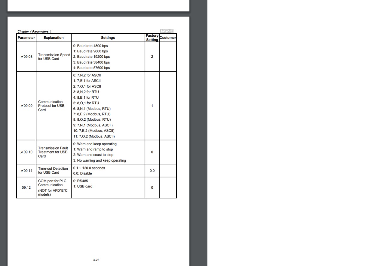
Vfdmod works in RTU mode, ASCII mode is not supported. According to your INI file I see communication speed is 9600 baud, 8N1. Be sure your VFD is configured on the same way: parameter 9.08 should be 1, and 9.09 should be 6. Also check VFD slave address, it should be set to 1 as it specified in your INI file.
Vfdmod works in RTU mode, ASCII mode is not supported. According to your INI file I see communication speed is 9600 baud, 8N1. Be sure your VFD is configured on the same way: parameter 9.08 should be 1, and 9.09 should be 6. Also check VFD slave address, it should be set to 1 as it specified in your INI file.
Please Log in or Create an account to join the conversation.
- taloot
- Offline
- Elite Member
-
Less
More
- Posts: 175
- Thank you received: 89
22 Jun 2020 00:38 #172289
by taloot
yeah i did same but no luck,,, i used the VFDB component and it works well i used ur generator to make the pyvcp and it work fine (after manually edit it ) ,,
i just need to add some monitoring parameter to source driver,, do u have any idea how can i compile the vfd , component submake file
Replied by taloot on topic [ Vfdmod ] An easy VFD control over MODBUS RTU
Hi taloot,
Vfdmod works in RTU mode, ASCII mode is not supported. According to your INI file I see communication speed is 9600 baud, 8N1. Be sure your VFD is configured on the same way: parameter 9.08 should be 1, and 9.09 should be 6. Also check VFD slave address, it should be set to 1 as it specified in your INI file.
yeah i did same but no luck,,, i used the VFDB component and it works well i used ur generator to make the pyvcp and it work fine (after manually edit it ) ,,
i just need to add some monitoring parameter to source driver,, do u have any idea how can i compile the vfd , component submake file
Please Log in or Create an account to join the conversation.
- aekhv
-
Topic Author
- Offline
- Senior Member
-
Less
More
- Posts: 49
- Thank you received: 18
22 Jun 2020 00:49 #172290
by aekhv
Replied by aekhv on topic [ Vfdmod ] An easy VFD control over MODBUS RTU
If you wish to modify vfdmod all you need is QtCreator: sudo apt install qtcreator.
Also it would be nice if you attach some debug output (loadusr -W vfdmod --debug ...), maybe it will help to fix your problem")
Also it would be nice if you attach some debug output (loadusr -W vfdmod --debug ...), maybe it will help to fix your problem
Please Log in or Create an account to join the conversation.
- SrLange61
-

- Offline
- Junior Member
-

Less
More
- Posts: 39
- Thank you received: 5
31 Dec 2020 09:48 #193621
by SrLange61
Replied by SrLange61 on topic [ Vfdmod ] An easy VFD control over MODBUS RTU
Hi
I'm trying to get my Fuling VFD from terminal control to Modbus with no luck. I've checked the 9600 n, 8, 1 settings on the VFD twice.
Any thoughts on this debug?
I'm trying to get my Fuling VFD from terminal control to Modbus with no luck. I've checked the 9600 n, 8, 1 settings on the VFD twice.
Any thoughts on this debug?
Attachments:
Please Log in or Create an account to join the conversation.
- aekhv
-
Topic Author
- Offline
- Senior Member
-
Less
More
- Posts: 49
- Thank you received: 18
31 Dec 2020 10:01 #193623
by aekhv
Replied by aekhv on topic [ Vfdmod ] An easy VFD control over MODBUS RTU
Hi, it looks like connection is not stable. Did you try another RS485 adapter? Also increasing of ProtocolDelay may help, check this parameter too.
The following user(s) said Thank You: SrLange61, aleksamc
Please Log in or Create an account to join the conversation.
- SrLange61
-
- Offline
- Junior Member
-
Less
More
- Posts: 39
- Thank you received: 5
01 Jan 2021 04:22 #193699
by SrLange61
Replied by SrLange61 on topic [ Vfdmod ] An easy VFD control over MODBUS RTU
Hi aekhv
Thanks for your quick reply last night and happy new year from Australia.
Increasing the ProtocolDelay to 7 fixed the com problem.
But now cant get the VFD to turn the spindle. Forward and Rev lights work on the VFD.
Looks like the Fuling needs special commands?
forum.pv-automation.com/viewtopic.php?p=52#p52
Any thoughts?
srl
Please Log in or Create an account to join the conversation.
- aekhv
-
Topic Author
- Offline
- Senior Member
-
Less
More
- Posts: 49
- Thank you received: 18
01 Jan 2021 04:44 #193700
by aekhv
Replied by aekhv on topic [ Vfdmod ] An easy VFD control over MODBUS RTU
Hi, happy new year too
As I see from debug output the control register address is 0x1000, and vfdmod sends 0x0005 to it. What values do you use to turn spindle on and off? According to table at your link it should be 0x0001 (run forward) and 0x0005 (stop).
Could you show your ini file please?
As I see from debug output the control register address is 0x1000, and vfdmod sends 0x0005 to it. What values do you use to turn spindle on and off? According to table at your link it should be 0x0001 (run forward) and 0x0005 (stop).
Could you show your ini file please?
Please Log in or Create an account to join the conversation.
- SrLange61
-
- Offline
- Junior Member
-
Less
More
- Posts: 39
- Thank you received: 5
01 Jan 2021 06:38 #193702
by SrLange61
Replied by SrLange61 on topic [ Vfdmod ] An easy VFD control over MODBUS RTU
Hi
I used the file vdf-dzb280.ini posted earlier in this thread, the control values are wrong.
The changed file attached.
All fine now.
No reverse but thats ok, setting foward run and fwd light up on the VFD. Reverse its stop and rev.
Thanks again.
srl
I used the file vdf-dzb280.ini posted earlier in this thread, the control values are wrong.
The changed file attached.
All fine now.
No reverse but thats ok, setting foward run and fwd light up on the VFD. Reverse its stop and rev.
Thanks again.
srl
Attachments:
Please Log in or Create an account to join the conversation.
Time to create page: 0.392 seconds