[ Vfdmod ] An easy VFD control over MODBUS RTU
- H2B
-

- Offline
- New Member
-

- Posts: 7
- Thank you received: 4
The data connection is simply 2 twisted wires (I'm using 18AWG, just because I didn't have a spare ethernet/telephone cable laying about), + to +, and - to -, and into a USB to serial adapter off amazon. Don't need to ground the signal wires at all. I did have to increase the default empty characters and time parameters in the .ini file to get it work reliably, so I'd recommend what I've already put in them in my earlier post as a starting point.
So here's what I set up, for 9600 baud, 8N1:
- F00.01: 2
- F00.06: 9
- F00.08: 0
- F00.09: 0
- F00.22: 9 (this was the missing piece of the puzzle for me, as I could see the H value changing, but not the P value)
- F13.00: 1
- F13.01: 5
- F13.02: 3
- F13.03: 20
- F13.04: 0.0
- F13.05: 1
That's about it! Good luck, should work for you, as long as you plug in your correct motor settings in the VFD and the .ini and .hal file properly!
Please Log in or Create an account to join the conversation.
- rodw
-

- Offline
- Platinum Member
-

- Posts: 11983
- Thank you received: 4082
I'm sure I have an issue with my TTY outputs.
The other one I found was a link on the board to enable RS485.
Can you expand on this comment of yours?
Unfortunately this model requires a reverse command to be sent using a negative percentage to the relative frequency command, which is something I'll try to figure out at a later stage.
Please Log in or Create an account to join the conversation.
- H2B
-
- Offline
- New Member
-
- Posts: 7
- Thank you received: 4
At least, that's what I've figured out. On page 160 of the manual, for address 0x1000H, the command for reverse spindle rotation is 0x0002 (they call it reverse running). If I issue that command to the VFD, it simply runs normally at the defined speed. To get it to run in reverse, you need to send, for example, -10000 to address 0x3000H (p161, first row of bottom table, left) for it to be recognized by the VFD as a 100% counter clockwise command to the drive. I haven't tested this out, as I'll have to modify the code and didn't have the time today, but that is what I've understood and observed from the docs.
Please Log in or Create an account to join the conversation.
- H2B
-
- Offline
- New Member
-
- Posts: 7
- Thank you received: 4
I've added some comments in the ini file that are unique to your setup. You'll need to know the max frequency of your VFD since some calculations are based on that to convert to/from speed commands.
[Common]
MaxSpeedRPM=2800
MinSpeedRPM=1
AtSpeedThreshold=0.01

[RS485]
SlaveAddress=1
SerialDevice=/dev/ttyUSB0
BaudRate=9600
DataBits=8
Parity=N
StopBits=2
ConnectionErrorList=5
ConnectionDelay=2000

[Control]
Address=0x40009
RunForwardValue=0x0002
RunReverseValue=0x0004
FaultResetValue=0x1000
StopValue=0x0200

[SpindleRpmIn]
FunctionCode=0x06
Address=0x40014
; the multiplier and divider should result in your RPM converted into a frequency value based on your drive
; for ex, if your max freq is 400Hz and your max speed is 2800 RPM, your M=400 and D=2800
Multiplier=1
Divider=2800

[SpindleRpmOut]
Address=0x40201
; the multiplier and divider should result in your RPM converted from a frequency value reported from the drive
; for ex, if your max freq is 400Hz and your max speed is 2800 RPM, your M=2800 and D=40000 since the docs state it returns in 0.01Hz/rpm (you need to *100 to get Hz)
Multiplier=2800
Divider=40000

[output-set-frequency]
; this is your requested setting, not the actual (which is SpindleRpmOut)
FunctionCode=0x03
Address0x40205
PinType=float
PinName=output-set-frequency
; the multiplier and divider should result in your RPM converted from a frequency value reported from the drive
; for ex, if your max freq is 400Hz and your max speed is 2800 RPM, your M=2800 and D=40000 since the docs state it returns in 0.01Hz/rpm (you need to *100 to get Hz)
Multiplier=2800
Divider=40000

[output-current]
FunctionCode=0x03
Address0x40202
PinType=float
PinName=output-current
Multiplier=100

[output-voltage]
FunctionCode=0x03
Address0x40203
PinType=float
PinName=output-voltage
Multiplier=10
Please Log in or Create an account to join the conversation.
- rodw
-
- Offline
- Platinum Member
-
- Posts: 11983
- Thank you received: 4082
I did not see any issues with forward and reverse. M3/M4 seemed to do the right thing.
I fitted this to a belt driven machine with 12 different gearing ratios so I'm not sure how to tackle that yet
I scaled it for the fastest speed.
I did notice the frequency output was not scaled correctly. It was out by a factor of 10
Please Log in or Create an account to join the conversation.
- H2B
-
- Offline
- New Member
-
- Posts: 7
- Thank you received: 4
From what I've understood of the vfdmod code so far, you'd have to perhaps create a custom python script to switch the values in runtime from a predefined variables file. Not trivial, but not too complicated btw. Maybe worth a feature request to the author of the mod?

I'll try running an M4 command, as I was using the CW/CCW default buttons in Axis to try the jog.
Please Log in or Create an account to join the conversation.
- rodw
-
- Offline
- Platinum Member
-
- Posts: 11983
- Thank you received: 4082
Please Log in or Create an account to join the conversation.
- Todd Zuercher
-

- Offline
- Platinum Member
-
- Posts: 4753
- Thank you received: 1458
Please Log in or Create an account to join the conversation.
- rodw
-
- Offline
- Platinum Member
-
- Posts: 11983
- Thank you received: 4082
Todd, thanks, Last night I wrote a component that lets me select the front belt and back belt and retrieve a scaling factor for the given belt combo based on some tacho data I collected earlier. Also paired it with an extension to the PYVCP panel. So I should be able to send the S command to the component which will scale it to correct Hz before sending it to the VFD.It is very common for VFDs to read the input for spindle speed to one decimal point. For example, you'd have to input 3000, for the drive to see 300.0hz.
I cheated though and hardcoded all of the ratios in the component.
Please Log in or Create an account to join the conversation.
- rodw
-
- Offline
- Platinum Member
-
- Posts: 11983
- Thank you received: 4082
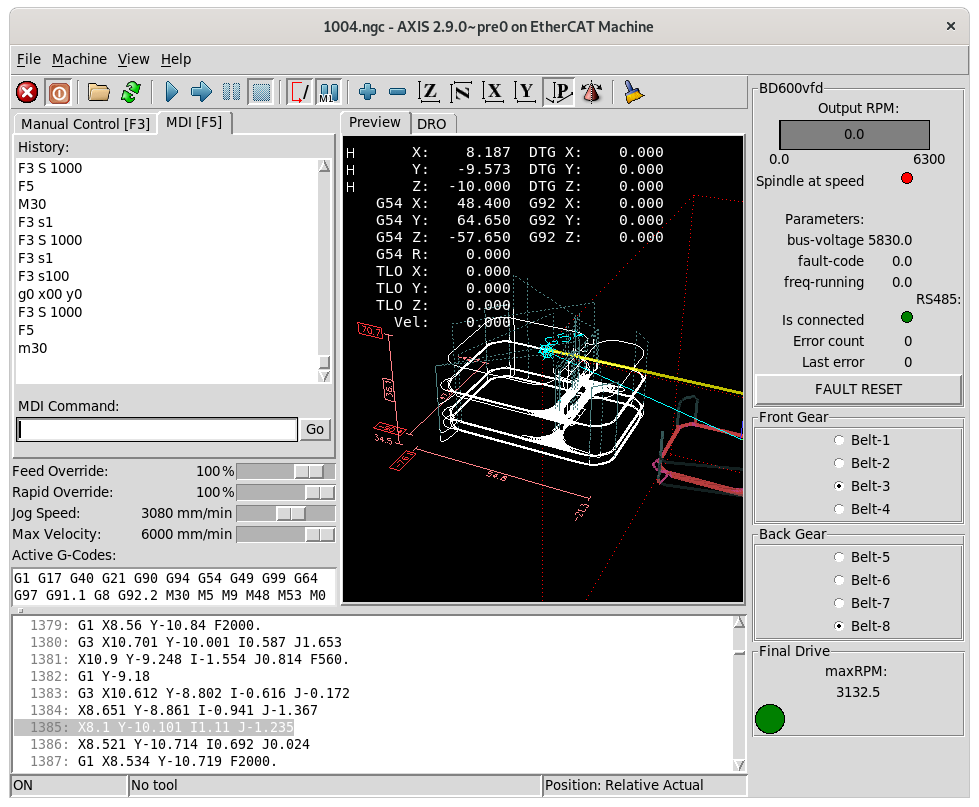
I asked for 1590 rpm and he tacho said it was doing 1599 rpm so close enough as there are lots of rounding and truncation errors.
Attachments:
Please Log in or Create an account to join the conversation.