Lathe conversion from stock to CNC
- Soundreflections
- Offline
- Senior Member
-

Less
More
- Posts: 56
- Thank you received: 0
01 Nov 2012 02:41 #26157
by Soundreflections
Replied by Soundreflections on topic Re:Lathe conversion from stock to CNC
Thanks Andy, I have thought I will get a second port, once my local supplier gets stock in. One can drive a machine with 4 O/P pins, as long as you can use serial MODBUS for the spindle, though I am now using PWM, so that all falls away.
When I have the basic system running I will add a second port, or expansion card, then start refining the machine.
When I have the basic system running I will add a second port, or expansion card, then start refining the machine.
Please Log in or Create an account to join the conversation.
- JamesNewton
- Offline
- New Member
-

Less
More
- Posts: 4
- Thank you received: 0
01 Nov 2012 04:26 #26164
by JamesNewton
Replied by JamesNewton on topic Re:Lathe conversion from stock to CNC
Let me know how it goes with those kits, Peet.
Andy, thanks for the referral. Let me know if you want to try one of the kits yourself, I'll make you a deal.
Andy, thanks for the referral. Let me know if you want to try one of the kits yourself, I'll make you a deal.
Please Log in or Create an account to join the conversation.
- Soundreflections
- Offline
- Senior Member
-
Less
More
- Posts: 56
- Thank you received: 0
03 Nov 2012 23:06 #26228
by Soundreflections
Replied by Soundreflections on topic Re:Lathe conversion from stock to CNC
I have decided to use the time I now have, waiting for my driver kits to develop my break out board and look at the mechanical mounting of everything.
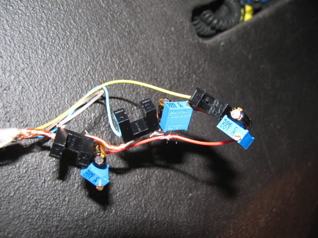
I did a very basic breakout board
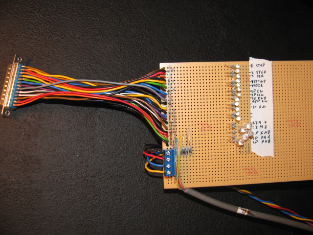
The optical spindle encoder initially gave me some hassles, but I found I was not driving the LED's hard enough, hence the variable resitors to set the current.
I then went and looked at my lathe's gearbox, to see what is practical.
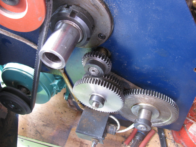
I plan on putting a stepper through on the right, driving the leadscrew instead of the power take off.
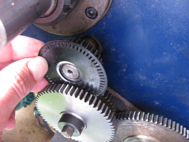
I had thought of interfacing with the main spindle directly, but there is not enough space to fit the encoder and optics, there is also no easy way to take a timing belt off it to a seperate box somewhere. I then looked at the power teke off, which is a scaled output, has a smaller diameter shaft, which I can turn an adaptor for. It also has enough space for me to mount the optical sensors, the best is it will have no real function in CNC mode. I am also concerned with LinuxCNC picking up all the pulses from a 59 slot disk? I still need to figure out how to tell LinuxCNC what scaling / PPR, etc to use.
Can LinuxCNC use a scaled index pulse, or should I keep that on the main spindle? I have thought about using the main gearbox, but cannot see a convenient way.
I would appreciate input and comments.
I did a very basic breakout board
The optical spindle encoder initially gave me some hassles, but I found I was not driving the LED's hard enough, hence the variable resitors to set the current.
I then went and looked at my lathe's gearbox, to see what is practical.
I plan on putting a stepper through on the right, driving the leadscrew instead of the power take off.
I had thought of interfacing with the main spindle directly, but there is not enough space to fit the encoder and optics, there is also no easy way to take a timing belt off it to a seperate box somewhere. I then looked at the power teke off, which is a scaled output, has a smaller diameter shaft, which I can turn an adaptor for. It also has enough space for me to mount the optical sensors, the best is it will have no real function in CNC mode. I am also concerned with LinuxCNC picking up all the pulses from a 59 slot disk? I still need to figure out how to tell LinuxCNC what scaling / PPR, etc to use.
Can LinuxCNC use a scaled index pulse, or should I keep that on the main spindle? I have thought about using the main gearbox, but cannot see a convenient way.
I would appreciate input and comments.
Please Log in or Create an account to join the conversation.
- BigJohnT
-

- Offline
- Administrator
-

Less
More
- Posts: 6999
- Thank you received: 1176
03 Nov 2012 23:31 #26229
by BigJohnT
Replied by BigJohnT on topic Re:Lathe conversion from stock to CNC
For threading you need one index per rev.
If your using hardware encoders they can keep up (I forget what your using).
John
If your using hardware encoders they can keep up (I forget what your using).
John
Please Log in or Create an account to join the conversation.
- Soundreflections
- Offline
- Senior Member
-
Less
More
- Posts: 56
- Thank you received: 0
03 Nov 2012 23:51 #26233
by Soundreflections
Replied by Soundreflections on topic Re:Lathe conversion from stock to CNC
I am using infra red optical interrupter type sensors.
I will put index on main spindle, that should be quite easy.
Are you suggesting I take phases off main index? Or will it be OK to get phases off the scaled output?
I want to start playing with the PWM to 0-10V conversion, but I cannot switch the machine on. I have posted this problem on another thread though.
Please Log in or Create an account to join the conversation.
- BigJohnT
-
- Offline
- Administrator
-
Less
More
- Posts: 6999
- Thank you received: 1176
04 Nov 2012 00:15 #26236
by BigJohnT
Replied by BigJohnT on topic Re:Lathe conversion from stock to CNC
I meant are you using a Mesa card or similar to count the encoder pulses then 59 slots is not a problem for sure, might be ok on the parallel port but I'm not good on math so I'll let someone else sort that out.
John
John
Please Log in or Create an account to join the conversation.
- Soundreflections
- Offline
- Senior Member
-
Less
More
- Posts: 56
- Thank you received: 0
04 Nov 2012 00:33 #26239
by Soundreflections
Replied by Soundreflections on topic Re:Lathe conversion from stock to CNC
I am using the parallel port straight at the moment, will sort the encoder once I have it on the machine.
Is there a way to display target RPM? If I start spindle it starts giving me PWM out, obviously faster and slower. I want to get a reference displayed, so that I can know what ratio to set on 0-10V?
Hope my question makes some sense!
Is there a way to display target RPM? If I start spindle it starts giving me PWM out, obviously faster and slower. I want to get a reference displayed, so that I can know what ratio to set on 0-10V?
Hope my question makes some sense!
Please Log in or Create an account to join the conversation.
- andypugh
-

- Offline
- Moderator
-

Less
More
- Posts: 23522
- Thank you received: 5005
04 Nov 2012 03:24 #26242
by andypugh
It needs to be exactly once per rev, but a simple flag on the spindle shaft will do.
The geared-down encoder is fine. Even if it turns out to have a non-integer number of pulses per rev (though that is vanishingly unlikely considering the function of the gear you are using)
Work out how many pulses per second there are at peak spindle speed, that will tell you if you have enough p-port sampling.
If you haven't it isn't a disaster, you only really need the encoder for threading, and you can do that at a speed where the parport can keep up.
You might find wiki.linuxcnc.org/cgi-bin/wiki.pl?Closed...pindle_Speed_Control
interesting
Replied by andypugh on topic Re:Lathe conversion from stock to CNC
Can LinuxCNC use a scaled index pulse, or should I keep that on the main spindle?
It needs to be exactly once per rev, but a simple flag on the spindle shaft will do.
The geared-down encoder is fine. Even if it turns out to have a non-integer number of pulses per rev (though that is vanishingly unlikely considering the function of the gear you are using)
Work out how many pulses per second there are at peak spindle speed, that will tell you if you have enough p-port sampling.
If you haven't it isn't a disaster, you only really need the encoder for threading, and you can do that at a speed where the parport can keep up.
You might find wiki.linuxcnc.org/cgi-bin/wiki.pl?Closed...pindle_Speed_Control
interesting
Please Log in or Create an account to join the conversation.
- Soundreflections
- Offline
- Senior Member
-
Less
More
- Posts: 56
- Thank you received: 0
04 Nov 2012 15:05 #26249
by Soundreflections
Replied by Soundreflections on topic Re:Lathe conversion from stock to CNC
It is great discovering the various documentations! Thanks for posting the applicable links.
I will have an un scaled index pulse, just scaled phase A&B, will try and figure out how to configure CNC with that later.
I have now told stepconf to use spindle at speed indicator, now it no longer creates the "bug", setting the LED after asking for it.
I have been thinking about things, I am using one input per axis for all 3 switches, so how is it going to discriminate between limit and home switches? Does it run over the first switch, till it hits the second, assuming that is the limit? How can I tell the system to use a limit switch as a home switch? That would surely make more sense?
I am starting to look at my physical machine, working out the best places for everything. My biggest current question is the home position. Where is the best place? I assume it will home if it wants to get it's tools changed? If it is too far out to the centre it could crash if one has the back rest advanced, and it could be too far off if one is making too small parts. Having it too near the head can leave less space for getting tools mounted.
I assume there is some procedure after every tool change to tell CNC how far the tool is offset in X & Z? Else it would have no form of accuracy. I have wondered, once I have the system running and I get a second parport, about having a X&Z sensor to detect tool position after every change, then the system can compensate itself for the offset.
Please Log in or Create an account to join the conversation.
- BigJohnT
-
- Offline
- Administrator
-
Less
More
- Posts: 6999
- Thank you received: 1176
04 Nov 2012 19:19 #26251
by BigJohnT
When combining the home and limit switch you don't physically have a home switch you use the limit switch to home to. When homing the software ignores the limit function if you set shared home and limit for that axis in the ini file. The important point about this is to set your home offset far enough from the switch so your not tripping the switch after the home move is complete as this will give you a limit error. Usually 0.125" - 0.250" is a good distance for home offset.
John
Replied by BigJohnT on topic Re:Lathe conversion from stock to CNC
I have been thinking about things, I am using one input per axis for all 3 switches, so how is it going to discriminate between limit and home switches? Does it run over the first switch, till it hits the second, assuming that is the limit? How can I tell the system to use a limit switch as a home switch? That would surely make more sense?
When combining the home and limit switch you don't physically have a home switch you use the limit switch to home to. When homing the software ignores the limit function if you set shared home and limit for that axis in the ini file. The important point about this is to set your home offset far enough from the switch so your not tripping the switch after the home move is complete as this will give you a limit error. Usually 0.125" - 0.250" is a good distance for home offset.
John
Please Log in or Create an account to join the conversation.
Moderators: piasdom
Time to create page: 0.154 seconds