My 7i76e Connection Sheet
- rodw
-

- Away
- Platinum Member
-

Less
More
- Posts: 12041
- Thank you received: 4108
02 Jan 2017 20:37 - 02 Jan 2017 20:39 #85116
by rodw
Replied by rodw on topic My 7i76e Connection Sheet
Thanks, If you had published this a week or so earlier, you would have saved me the cost of the power supply 
The advantage of using 2 power supplies is that this does not apply.
"When the on card regulator is used, the maximum power available from the encoder, serial, and 26 pin expansion connectors is 2A total."
The only thing that I've noted is missing is connecting a THCAD for plasma
TB3.01 -> THCAD.P1.1 +5 V
TB3.07 -> THCAD.P1.2 FOUT+
TB3.08 -> THCAD.P1.3 FOUT-
TB3.06 -> THCAD.P1.6 -5 V
Of course, there are other pins available to obtain 5 volt power for the THCAD
Last edit: 02 Jan 2017 20:39 by rodw.
Please Log in or Create an account to join the conversation.
- newbynobi
-
 Topic Author
- Offline
- Platinum Member
-
Less
More
- Posts: 1931
- Thank you received: 394
03 Jan 2017 17:21 #85148
by newbynobi
Replied by newbynobi on topic My 7i76e Connection Sheet
Hallo rodw,
thanks for the Information.
The Pins you mentioned are metioned in my config for other purpose.
Norbert
thanks for the Information.
The Pins you mentioned are metioned in my config for other purpose.
Norbert
Please Log in or Create an account to join the conversation.
- Gommiswald
- Offline
- Junior Member
-

Less
More
- Posts: 32
- Thank you received: 0
15 Apr 2017 08:42 #91397
by Gommiswald
Replied by Gommiswald on topic My 7i76e Connection Sheet
Hi
I'm new to the forum and also new with Linuxcnc. But I managed to install a MESA 7i76e in Linuxcnc 2.7. My question now concerns the following question: Can I connect directly the output signal of a 24V 3-wire NPN Omron EE-SX670A (NPN) to 5V logic (Index hookup of the Encoder part on TB 3). And can I also use the output signal of a second NPN Omron EE-SX670A with the encoder connector A? The signal of a perforated disc with 12 holes is read off. - Thank you very much for your help!
I'm new to the forum and also new with Linuxcnc. But I managed to install a MESA 7i76e in Linuxcnc 2.7. My question now concerns the following question: Can I connect directly the output signal of a 24V 3-wire NPN Omron EE-SX670A (NPN) to 5V logic (Index hookup of the Encoder part on TB 3). And can I also use the output signal of a second NPN Omron EE-SX670A with the encoder connector A? The signal of a perforated disc with 12 holes is read off. - Thank you very much for your help!
Please Log in or Create an account to join the conversation.
- tommylight
-

- Away
- Moderator
-

Less
More
- Posts: 21747
- Thank you received: 7433
15 Apr 2017 09:55 #91402
by tommylight
Double post !
Never connect 24V parts to 5V parts without voltage dividers, they are simple stuff made by 2 resistors in case of signaling.
Replied by tommylight on topic My 7i76e Connection Sheet
Hi
I'm new to the forum and also new with Linuxcnc. But I managed to install a MESA 7i76e in Linuxcnc 2.7. My question now concerns the following question: Can I connect directly the output signal of a 24V 3-wire NPN Omron EE-SX670A (NPN) to 5V logic (Index hookup of the Encoder part on TB 3). And can I also use the output signal of a second NPN Omron EE-SX670A with the encoder connector A? The signal of a perforated disc with 12 holes is read off. - Thank you very much for your help!
Double post !
Never connect 24V parts to 5V parts without voltage dividers, they are simple stuff made by 2 resistors in case of signaling.
Please Log in or Create an account to join the conversation.
- DanMN
-

- Offline
- Senior Member
-

Less
More
- Posts: 74
- Thank you received: 10
17 Apr 2017 21:42 #91553
by DanMN
Replied by DanMN on topic My 7i76e Connection Sheet
This is a very helpful guide for getting started -- thank you for it! Can anyone explain how I would connect/configure normally open NPN prox sensors correctly? I realize they are not the optimal choice, but they are what I'm currently stuck with. I'm powering them at 24v, directly from the power suppl. They push +24v to the input pins when not activated then when activated they flip to ground. Is this OK?
Thanks again.
Thanks again.
Please Log in or Create an account to join the conversation.
- PCW
-

- Offline
- Moderator
-
Less
More
- Posts: 17991
- Thank you received: 5281
17 Apr 2017 21:58 - 17 Apr 2017 21:59 #91557
by PCW
Replied by PCW on topic My 7i76e Connection Sheet
Typically NPN proximity switches would need a relatively stiff pullup resistor (say 2K 1/2W) to 24V
to work with the 7I76E's sinking inputs (because a bare NPN output can only sink current to ground)
If they output +24V into the 7I76E inputs wihout added components,
it likely means they are either not NPN sensors, or they have built in
pullup resistors or push-pull outputs.
to work with the 7I76E's sinking inputs (because a bare NPN output can only sink current to ground)
If they output +24V into the 7I76E inputs wihout added components,
it likely means they are either not NPN sensors, or they have built in
pullup resistors or push-pull outputs.
Last edit: 17 Apr 2017 21:59 by PCW.
The following user(s) said Thank You: DanMN
Please Log in or Create an account to join the conversation.
- DanMN
-
- Offline
- Senior Member
-
Less
More
- Posts: 74
- Thank you received: 10
17 Apr 2017 22:29 #91559
by DanMN
Replied by DanMN on topic My 7i76e Connection Sheet
Thanks for the reply. I have 8 of the sensors in the pic attached (min/max on every joint of a gantry router). They are apparently acting as they are designed, as confirmed by some Googling and YouTube demos of the product. I have some 2k/1w resistors in the parts bin, but lacking any direct experience from others using this type with the 7i76e I'm concerned about unforeseen consequences. I'm learning as I go.
If I've just got the wrong product, I can fall on my sword and buy new PNPs -- but if there is a way to make it work with what I've got, that would be preferable. I welcome any informed opinions -- if I should not bother wasting my time with a patchwork mish-mash, don't be afraid to say so")
If I've just got the wrong product, I can fall on my sword and buy new PNPs -- but if there is a way to make it work with what I've got, that would be preferable. I welcome any informed opinions -- if I should not bother wasting my time with a patchwork mish-mash, don't be afraid to say so
Please Log in or Create an account to join the conversation.
- rodw
-
- Away
- Platinum Member
-
Less
More
- Posts: 12041
- Thank you received: 4108
17 Apr 2017 23:11 #91560
by rodw
Replied by rodw on topic My 7i76e Connection Sheet
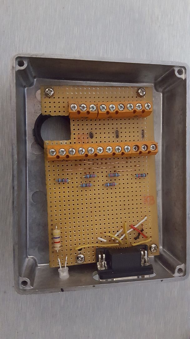
I made the same mistake and use the pull up resistors as PCW has said and they work fine. You can see the resistors spanning between the output and +24V in this pic.
Please Log in or Create an account to join the conversation.
- DanMN
-
- Offline
- Senior Member
-
Less
More
- Posts: 74
- Thank you received: 10
18 Apr 2017 01:40 #91562
by DanMN
Replied by DanMN on topic My 7i76e Connection Sheet
OK, my education continues. I think I'm vaguely starting to get it. I have my inputs configured like the diagram from the OP's Connection Sheet -- with one difference: my sensor is N.O., where his is N.C. Each of my 8 leads go into pins 4-12 on the 7i76e's TB6 connector.
On their way to the input pin, each signal lead gets a T-spliced connection to the +24v side of the power supply through a 2k 1w resistor -- but I'm not sure how this matters, since the sensor itself feeds +24v straight through on it's black wire when it is open. When it detects nearby metal, the +24v toggles to Ground on the black wire. The net is, if I measure voltage on the input pins via their screw heads, that voltage is always +24v while the sensor detects nothing.
Is +24v going into the TB6 input pins OK?
Attached is a photo of the sticker on my sensor. The manufacturer refers to this sticker "the manual" -- yep, that's IT. It appears to show what I believe PCW suggested in his previous post -- that the pullup is built in? The rectangle with the diagonal slash through it is spanning between the signal wire and positive, with "300mA" defined. Does that make the additional resistors unnecessary?
Finally, the difference between the diagram in the OP and my setup: since I'm normally open, the input pin sees "high" until detection, then it sees Ground. Would my configuration just need to invert the signal in linuxcnc to indicate triggering, where this OP's config would show High as a trigger?
Thanks for the patience and shared experience. I've been dabbling at this build for months, and it's so close...yet so far...
Please Log in or Create an account to join the conversation.
- rodw
-
- Away
- Platinum Member
-
Less
More
- Posts: 12041
- Thank you received: 4108
18 Apr 2017 01:55 #91563
by rodw
Replied by rodw on topic My 7i76e Connection Sheet
I don't think you have a pullup resistor. The "manual" shows a load (whatever you are switching). The NO and NC just says what is the state without the sensor near some metal. So a NC switch will have +24v on the output away from metal and the NC will have +24v on the output while close to metal. Hope I got that the right way round. BEst bet is to hook it up to a power supply and play with a multimeter.
I think you will find that you will get spurious activity on the output without the pull up resistor on an NPN sensor...
This video explains it very well
I think you will find that you will get spurious activity on the output without the pull up resistor on an NPN sensor...
This video explains it very well
The following user(s) said Thank You: DanMN
Please Log in or Create an account to join the conversation.
Moderators: PCW, jmelson
Time to create page: 0.149 seconds