My 7i76e Connection Sheet
- Gommiswald
- Offline
- Junior Member
-

Less
More
- Posts: 32
- Thank you received: 0
18 Apr 2017 20:04 #91598
by Gommiswald
Replied by Gommiswald on topic My 7i76e Connection Sheet
Sorry for the double post!!! I didn't know where to post my question.
623/5000
My solution is now that I connect the OMRON sensors to 5VDC.
Another question: Beckhoff AX2500 needs differential voltage signals (+ 10V / -10V) for the frequency and direction of rotation. (A servomotor as main spindle drive). Can one now simply connect Spindle + and Spindle - with the drive connections and the should then function? So spindle+ and spindle- means differential output?
And lastly: Why not switch a relay between the inductive proximity switches and the 7I76E connections? 24V switched by the FieldPower connection via a relay? There would be the whole thing with the resistance simply fall away?
Please Log in or Create an account to join the conversation.
- tommylight
-

- Away
- Moderator
-

Less
More
- Posts: 21747
- Thank you received: 7433
18 Apr 2017 21:41 #91607
by tommylight
More expencive, more work. Much safer and fully isolated from the machine.
Replied by tommylight on topic My 7i76e Connection Sheet
I do that for plasma cutters to limit imterferences, namely every limit switch and float switch has a relay power by 24V, the contacts just short the inputsbto the ground. Normaly closed limit switches, so whatever breaks betveen them, i get an error.And lastly: Why not switch a relay between the inductive proximity switches and the 7I76E connections? 24V switched by the FieldPower connection via a relay? There would be the whole thing with the resistance simply fall away?
More expencive, more work. Much safer and fully isolated from the machine.
Please Log in or Create an account to join the conversation.
- Gommiswald
- Offline
- Junior Member
-
Less
More
- Posts: 32
- Thank you received: 0
14 May 2017 20:55 #93199
by Gommiswald
Replied by Gommiswald on topic My 7i76e Connection Sheet
Hi
Now my little selfmade CNC Lathe works fine with the 7i76e Mesa Card. A great card with great functions. The problem with the feedback I solved from one side with the encoder output of the Beckhoff AX servo drive and the Index Signal I take from the Omron photosensor. I didn't need to change the voltage from 24 to 5V. I just connected the signal to an optocoupler relay and then to the encoder part of the 7i76e. First I had some problem, because I didn't get an index signal. This index signal is single ended and the signal A and B are differential. But at the moment, when I took away the connections of A- and B- and installed the jumpers 10-13 in the right order, the index signal runs great, so G76 threading works wonderful.
My experience is the one, that one has to try and change and try, until it works. But it is great, that there is a forum and I used it very often until the lathe worked as it has to work!
Best regards
Daniel
Please Log in or Create an account to join the conversation.
- Gommiswald
- Offline
- Junior Member
-
Less
More
- Posts: 32
- Thank you received: 0
19 Dec 2017 20:19 #103360
by Gommiswald
Replied by Gommiswald on topic My 7i76e Connection Sheet
Hi Norbert
Thanks a lot for your wiring diagram. A really great helpful piece of work. Just one question. I want to add an analog in on input 0 for feed override for my Schaublin 128CNC retrofit. Have you maybe a link for a HAL example to configure this analog- in "feed override".
Regards from Switzerland
Daniel
Please Log in or Create an account to join the conversation.
- rodw
-

- Away
- Platinum Member
-

Less
More
- Posts: 12041
- Thank you received: 4108
19 Dec 2017 21:31 #103363
by rodw
Replied by rodw on topic My 7i76e Connection Sheet
Daniel, thats a really good idea and you would probably get more people to look at your question if you raised a seperate thread.
I think it would be pretty easy to do. The 7i76e has analog voltage pins that return the voltage read. Say you put a potentiometer on the field power (I will assume 24 volts), you would need to pick a voltage to represent zero override (say 12 volts). you could use mult2 (with the inverse of 12) to set a 0% to 200% range (0.0-2.0) If say you wanted to limit the control to only allow say 80% to 120% , you could use the scale component to achieve this.
I think it would be pretty easy to do. The 7i76e has analog voltage pins that return the voltage read. Say you put a potentiometer on the field power (I will assume 24 volts), you would need to pick a voltage to represent zero override (say 12 volts). you could use mult2 (with the inverse of 12) to set a 0% to 200% range (0.0-2.0) If say you wanted to limit the control to only allow say 80% to 120% , you could use the scale component to achieve this.
Please Log in or Create an account to join the conversation.
- andypugh
-

- Offline
- Moderator
-
Less
More
- Posts: 19879
- Thank you received: 4643
24 Dec 2017 00:53 #103502
by andypugh
Replied by andypugh on topic My 7i76e Connection Sheet
Check the manual, some analogue inputs on some boards (7i64 for example) are 3.3V max.
Please Log in or Create an account to join the conversation.
- rodw
-
- Away
- Platinum Member
-
Less
More
- Posts: 12041
- Thank you received: 4108
24 Dec 2017 00:59 #103503
by rodw
The 7i76e analog inputs discussed on this thread are 8 bit, 36.3 volts full scale with an accuracy of +-5%
Replied by rodw on topic My 7i76e Connection Sheet
Check the manual, some analogue inputs on some boards (7i64 for example) are 3.3V max.
The 7i76e analog inputs discussed on this thread are 8 bit, 36.3 volts full scale with an accuracy of +-5%
The following user(s) said Thank You: Clive S
Please Log in or Create an account to join the conversation.
- +Jan+
- Offline
- Senior Member
-

Less
More
- Posts: 61
- Thank you received: 16
30 Dec 2017 14:29 - 30 Dec 2017 14:30 #103851
by +Jan+
Replied by +Jan+ on topic My 7i76e Connection Sheet
Hello,
I think this might fit here, some days ago I made labels for the clamping brackets of the 7i76:
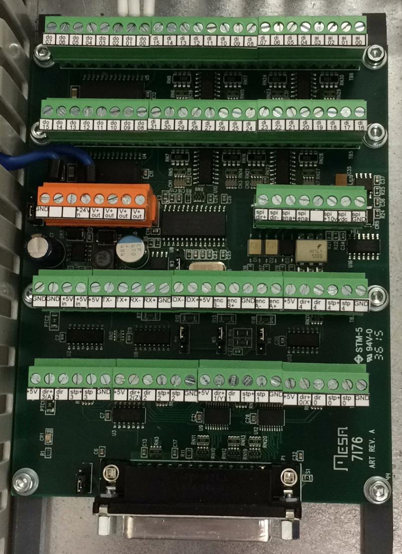
I attach the pdf and dxf file. I`ve printed them sticked them on doublesided tape.
Best wishes
Jan
I think this might fit here, some days ago I made labels for the clamping brackets of the 7i76:
I attach the pdf and dxf file. I`ve printed them sticked them on doublesided tape.
Best wishes
Jan
Last edit: 30 Dec 2017 14:30 by +Jan+.
The following user(s) said Thank You: phillc54, tecno, snoozer77, silopolis, The_wolf_of_walmart, palmac, Flyer007 and 2 other people also said thanks.
Please Log in or Create an account to join the conversation.
- tecno
-

- Offline
- Platinum Member
-
Less
More
- Posts: 1850
- Thank you received: 127
30 Dec 2017 14:36 #103852
by tecno
Replied by tecno on topic My 7i76e Connection Sheet
Nice job Jan
Please Log in or Create an account to join the conversation.
- Moronicsmurf
-

- Offline
- Senior Member
-
Less
More
- Posts: 53
- Thank you received: 2
30 Dec 2017 15:24 #103854
by Moronicsmurf
Replied by Moronicsmurf on topic My 7i76e Connection Sheet
Very nice, this will help a bundle. =)
Please Log in or Create an account to join the conversation.
Moderators: PCW, jmelson
Time to create page: 0.193 seconds