My 7i76e Connection Sheet
- PCW
-

- Offline
- Moderator
-

Less
More
- Posts: 17991
- Thank you received: 5281
14 Nov 2020 21:09 #189377
by PCW
Replied by PCW on topic My 7i76e Connection Sheet
Did you check that the switches operate?
That is can you can see the hal pins changing when you activate the switch?
You can check these with halshow "watch" function
In axis this is in the Machine --> Show Hal Configuration ---> Watch menu
The 7i76 input pins would be in Pins --> hm2_7i76e --> 7i76 --> input-xx
That is can you can see the hal pins changing when you activate the switch?
You can check these with halshow "watch" function
In axis this is in the Machine --> Show Hal Configuration ---> Watch menu
The 7i76 input pins would be in Pins --> hm2_7i76e --> 7i76 --> input-xx
Please Log in or Create an account to join the conversation.
- fons
-
- Offline
- Senior Member
-

Less
More
- Posts: 61
- Thank you received: 0
14 Nov 2020 22:24 #189395
by fons
Replied by fons on topic My 7i76e Connection Sheet
i see the signal in the halshow and its what i expect its inverted because of the sensor and now i see it as a high level when the switch is activated
Please Log in or Create an account to join the conversation.
- fons
-
- Offline
- Senior Member
-
Less
More
- Posts: 61
- Thank you received: 0
17 Nov 2020 23:01 #189633
by fons
Replied by fons on topic My 7i76e Connection Sheet
i make a macro for automatic tool length setting in the table
it look like this (without the line numbers)
1: o<tool-lengte> sub
2: G21
3: G91 G38.2 F150 Z-10
4: G90 G0 Z[#5063+.25]
5: G91 G38.2 F5 Z-.5
6: G10 L1 P#5400 Z#5063
7: (debug, tool is nu 10 mm boven vlak)
8: G91 G0 Z10
9: o<tool-lengte> endsub
10: M2
this give an error " p value out of range with G10 L1 "
when i change line 6 into 6: "G10 L1 P2 Z#5063" it store the value in the table on tool 2
offcource the value #5400 is wrong i don't find a better one
what is the correct spelling or an example of a macro for these operation
Please Log in or Create an account to join the conversation.
- Muzzer
- Offline
- Elite Member
-

Less
More
- Posts: 266
- Thank you received: 42
18 Nov 2020 15:37 #189681
by Muzzer
Replied by Muzzer on topic My 7i76e Connection Sheet
I'm confused about TB3 power connections. The Mesa manual says:
"CABLE 5V POWER
The 7I76 can get its 5V encoder, step/dir and serial interface power from the host interface card if desired. W2 determines if the 7I76 gets this 5V power from the host FPGA card. If W2 is in the left hand position, host cable power is used. If W2 is in the right hand position, 5V power must be supplied to the 7I76 via TB3. This option must be set to match the cable power option of the host FPGA card. If the FPGA card supplies 5V, W2 must be in the left hand position. If the FPGA card does not supply 5V, W2 must be in the right hand position. Never apply external 5V power to the 7I76's TB3 connector when W2 is in the left hand position or you may damage the 7I76, FPGA card, PC, or connecting cable."
Later on (page 6), the terminal idents show "+5V supply power" on pin 22.
Strikes me that I'd be brave or foolhardy to decide that the above means I should apply 24V to pin 22, yet Norbert's connection sheet shows just that. Perhaps I've missed something here but the manual is commendably brief.
I've got the W2 header set to take power from the 5i25 but I'm still confused. I suppose I could see what happens if I swap it across but with the price of the 7i76 that doesn't seem the right approach. Is there a regulator between pin 22 and the 5V node? Can I safely apply 24V to pin 22?
Thanks
Please Log in or Create an account to join the conversation.
- PCW
-
- Offline
- Moderator
-
Less
More
- Posts: 17991
- Thank you received: 5281
18 Nov 2020 16:09 - 18 Nov 2020 16:11 #189686
by PCW
Replied by PCW on topic My 7i76e Connection Sheet
The 7I76 and 7I76E are very different with regard to power connections.
They are not comparable at all. If you apply 24V to a 7I76s P3 pin 22
you will destroy the card since that is a 5V power connection
They are not comparable at all. If you apply 24V to a 7I76s P3 pin 22
you will destroy the card since that is a 5V power connection
Last edit: 18 Nov 2020 16:11 by PCW.
Please Log in or Create an account to join the conversation.
- Muzzer
- Offline
- Elite Member
-
Less
More
- Posts: 266
- Thank you received: 42
18 Nov 2020 16:25 #189689
by Muzzer
Replied by Muzzer on topic My 7i76e Connection Sheet
Thanks - good to know. Would be easy to get bitten there.
Please Log in or Create an account to join the conversation.
- fons
-
- Offline
- Senior Member
-
Less
More
- Posts: 61
- Thank you received: 0
21 Nov 2020 00:11 #189937
by fons
Replied by fons on topic My 7i76e Connection Sheet
G10 L1 P#5400 Z#5063
with this sentence i will place the tool length in the table
only i can't find the right value for "p" to do that automatic when i place p2 the toollength wil be placed in table with tool 2
with this sentence i will place the tool length in the table
only i can't find the right value for "p" to do that automatic when i place p2 the toollength wil be placed in table with tool 2
Please Log in or Create an account to join the conversation.
- EisbaerLars
- Offline
- New Member
-

Less
More
- Posts: 4
- Thank you received: 12
09 Jan 2021 23:34 - 10 Jan 2021 14:32 #194655
by EisbaerLars
Replied by EisbaerLars on topic My 7i76e Connection Sheet
Combined the efforts of @my.cnc.brother (
here
)
and @+Jan+ earlier in this post to the attached labels for the front and top of the Mesa 7i76e connectors
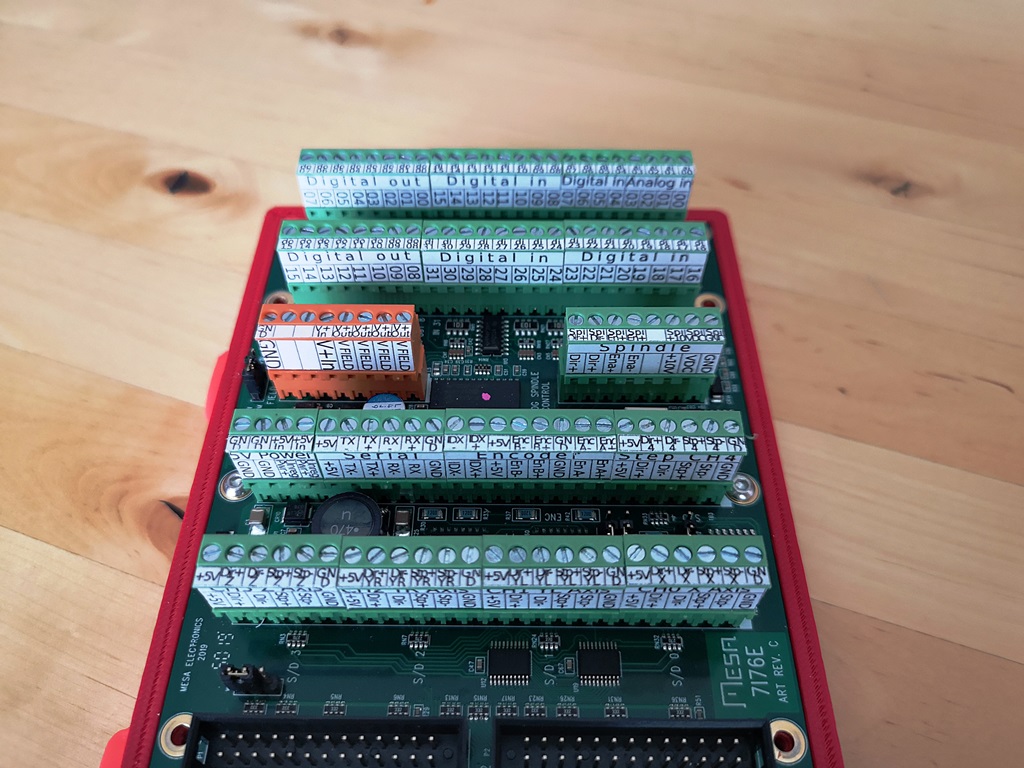
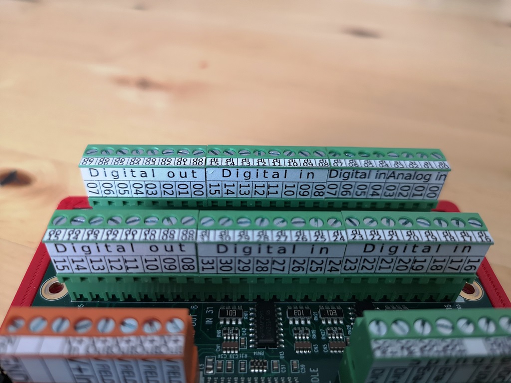
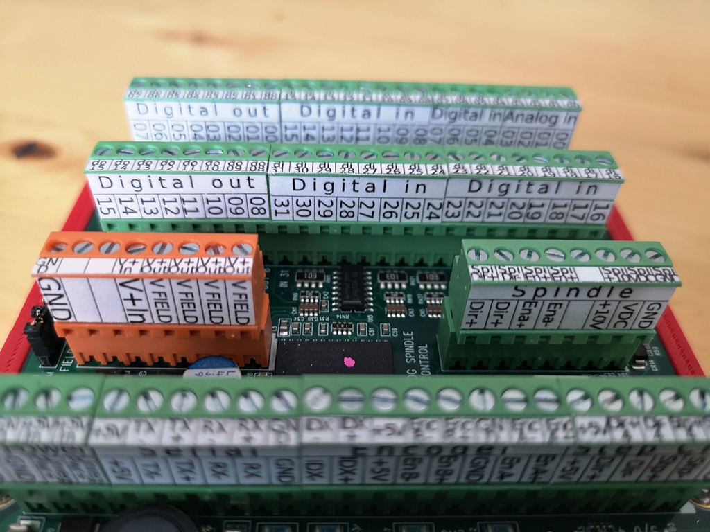
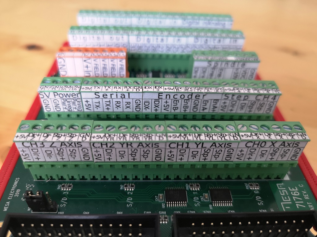
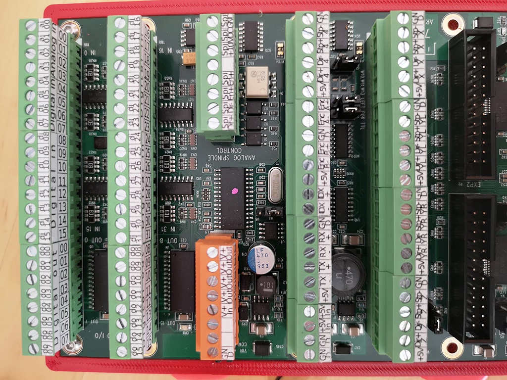
and @+Jan+ earlier in this post to the attached labels for the front and top of the Mesa 7i76e connectors
Last edit: 10 Jan 2021 14:32 by EisbaerLars.
The following user(s) said Thank You: tommylight, faeluke, Muftijaja, ggsxx, P1-Engineering
Please Log in or Create an account to join the conversation.
- EisbaerLars
- Offline
- New Member
-
Less
More
- Posts: 4
- Thank you received: 12
01 Feb 2021 01:20 #197267
by EisbaerLars
Replied by EisbaerLars on topic My 7i76e Connection Sheet
And here are the labels for the Mesa 7i96 top and front
Attachments:
The following user(s) said Thank You: tommylight, +Jan+, Sadmeatball, fons, Muftijaja
Please Log in or Create an account to join the conversation.
- franstrein
- Offline
- Junior Member
-

Less
More
- Posts: 27
- Thank you received: 2
01 Feb 2021 13:39 #197303
by franstrein
Replied by franstrein on topic My 7i76e Connection Sheet
Hi ,
Thanks for this labels file for a 7i96.
Is anyone having anything like that for a 7i85S as well?
If not, could you share the original (Word?) document you used to make this?
Thanks,
Frans
Thanks for this labels file for a 7i96.
Is anyone having anything like that for a 7i85S as well?
If not, could you share the original (Word?) document you used to make this?
Thanks,
Frans
Please Log in or Create an account to join the conversation.
Moderators: PCW, jmelson
Time to create page: 1.049 seconds