My 7i76e Connection Sheet
- Aciera
-

- Online
- Administrator
-

- Posts: 4755
- Thank you received: 2135
Thanks again for the connection sheets.
However there seems to be a minor flaw in it concerning the Field Power connection as pointed here out by PCW: forum.linuxcnc.org/plasma-laser/40517-do...ons?start=120#193043
Nothing should connect to TB1 pin 5 (VIN)
VFIELD (TB1 pins 1..4) is where +24V power goes
From the manual:
The isolated field I/O on the 7I76E runs from a switching power supply that can be powered by field power or a separate supply (VIN) with ground common with field power.Normally the 7I76E will be powered with field power and an on card jumper, W1 allows VIN to be connected to field power. If you wish to use a single power supply for the 7I76Es field outputs and field logic power, W1 should be placed in the left hand position. This connects field power to VIN. If you wish to use a separate supply for VIN, W1 Should be placed in the right hand position.
Your schematics works but the bulk of the field power current goes through the Jumper W1 instead of just the power for the field I/O processor. Also manipulation of the jumper when powered might damage the output drivers.
Please Log in or Create an account to join the conversation.
- BeagleBrainz
-

- Visitor
-

With VField @ 24v a 2k 0.5 Watt resistor would suffice per input ?
(24^2)/2000 = 0.288W
As the alarm output from the driver pulses a 1hz the HAL flip flop comp would be the best way to catch the alarm signal ?
Please Log in or Create an account to join the conversation.
- PCW
-

- Offline
- Moderator
-

- Posts: 17991
- Thank you received: 5281
if the optocoupler can supply 24V to an input an pullup resistor is not needed
2K 1/2 W should be fine if a pullup is needed
A flipflop component with its clock driven by the alarm signal
(and data pin tied to '1') can detect the alarm signal
A better choice might be the oneshot component set for a bit over 1/2 second
The oneshot component has the advantage that it can be set up to trigger
on both edges of the alarm signal and may not require resetting
Please Log in or Create an account to join the conversation.
- BeagleBrainz
-
- Visitor
-
I’ll look into the one shot as well.
Once again thanks for your help.
Please Log in or Create an account to join the conversation.
- fons
-
- Offline
- Senior Member
-

- Posts: 61
- Thank you received: 0
Please Log in or Create an account to join the conversation.
- PCW
-
- Offline
- Moderator
-
- Posts: 17991
- Thank you received: 5281
(or a 7I73 could be added to the serial expansion port, adding 4 more MPG channels)
Please Log in or Create an account to join the conversation.
- fons
-
- Offline
- Senior Member
-
- Posts: 61
- Thank you received: 0
i have 4 speed settings combined 16 gears
28 35 45 56 70 90 112 140 180 224 280 355 450 560 700 900 rpm
i will us use a vfd to control the motor 1450rpm 7.5kw
Please Log in or Create an account to join the conversation.
- Ironmadnes
- Offline
- New Member
-

- Posts: 6
- Thank you received: 1
Please Log in or Create an account to join the conversation.
- Karri
- Offline
- New Member
-
- Posts: 18
- Thank you received: 1
Could someone double check my schema to use 12V as logic power and 5V as field power
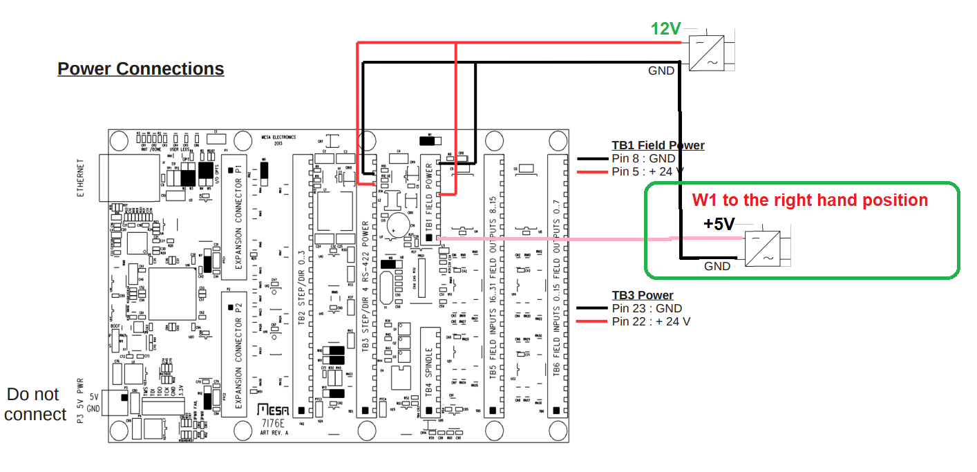
BR:Karri
Attachments:
Please Log in or Create an account to join the conversation.
- fons
-
- Offline
- Senior Member
-
- Posts: 61
- Thank you received: 0
just conect the power conector tb1
gnd at pin 8 (the side of the board) + 12v (+24v) at pin 2
it look like pin 1, 2, 3, 4 and 5 are the same and give power to tb6 and tb5
on tb6 are no gnd conections to make only one common gnd conected to pin 8 on tb4
pin 1 to 4 can be used as analog or digital input
pin 5 to 16 are digital input
pin 17 to 24 are digital output
Please Log in or Create an account to join the conversation.