ColorCNC Colorlight 5A-75E/5A-75B as FPGA controller board
- muvideo
- Offline
- Senior Member
-

Less
More
- Posts: 62
- Thank you received: 30
05 Jun 2022 20:19 #244639
by muvideo
Replied by muvideo on topic ColorCNC Colorlight 5A-75E/5A-75B as FPGA controller board
Hi, the pinout I'm using with 5a75e V8 Is the default 5a75e v6
The following user(s) said Thank You: svb
Please Log in or Create an account to join the conversation.
- TOLP2
- Offline
- Elite Member
-

Less
More
- Posts: 225
- Thank you received: 178
06 Jun 2022 12:15 - 06 Jun 2022 20:07 #244661
by TOLP2
Replied by TOLP2 on topic ColorCNC Colorlight 5A-75E/5A-75B as FPGA controller board
@muvideo: It is indeed the case that the write buffer in your case is too big, causing a shift in the data read from the device. The suspect is the encoder you added in the config file. The encoders are not finished yet and not tested either. Can you try to remove the encoders from the config-file and recompile both the firmware and the driver.
Edit: I have updated the algorithm of the stepgen's to get more smooth behavior when the acceleration limit is not obeyed by the motion planner (or you're using not a motion planner, but siggen instead). I tested it with a square wave from siggen and it looks very smooth. Basically, as soon the stepgen cannot follow the commanded position, it will set the `catching_up` flag. The speed is increased using the maximum acceleration (97.5% of maximum value, a small overhead is kept for catching up with small deviations from the perfect path). The speed is increased until the maximum speed, which is based on the error and the time it takes to take to decelerate to the normal speed (to prevent overshoot). The resulting graph is now as shown below.
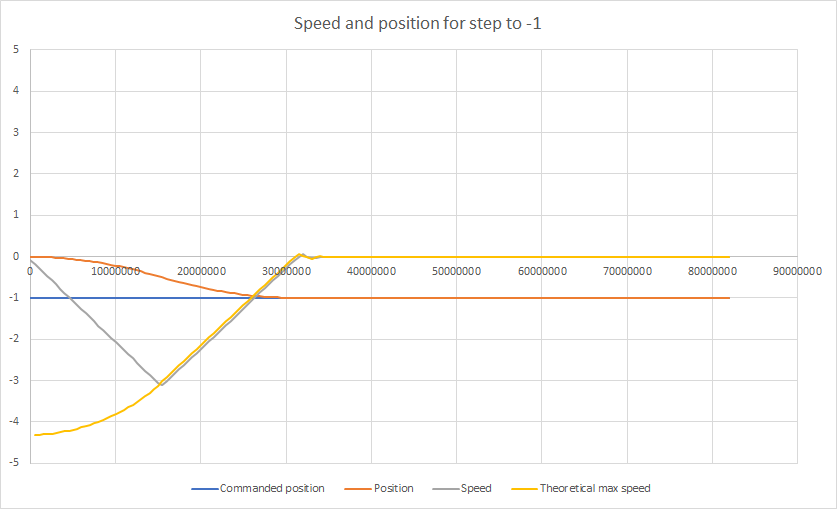
Edit 2: Fixed the last overshoot
Edit: I have updated the algorithm of the stepgen's to get more smooth behavior when the acceleration limit is not obeyed by the motion planner (or you're using not a motion planner, but siggen instead). I tested it with a square wave from siggen and it looks very smooth. Basically, as soon the stepgen cannot follow the commanded position, it will set the `catching_up` flag. The speed is increased using the maximum acceleration (97.5% of maximum value, a small overhead is kept for catching up with small deviations from the perfect path). The speed is increased until the maximum speed, which is based on the error and the time it takes to take to decelerate to the normal speed (to prevent overshoot). The resulting graph is now as shown below.
Edit 2: Fixed the last overshoot
Attachments:
Last edit: 06 Jun 2022 20:07 by TOLP2. Reason: Added stepgen progress
Please Log in or Create an account to join the conversation.
- TOLP2
- Offline
- Elite Member
-
Less
More
- Posts: 225
- Thank you received: 178
06 Jun 2022 13:51 - 06 Jun 2022 13:51 #244666
by TOLP2
Replied by TOLP2 on topic ColorCNC Colorlight 5A-75E/5A-75B as FPGA controller board
@svb: The error you see is most likely not the cause of the json not being linked. I think that when the packet is received, something is not up to the liking of the driver. An error occurs in the the error handling.
Could you please do the following:
1) ping the board to make sure it can be reached (the ping command is outside halrun);
2) if possible, try to use LinuxCNC 2.8.x. This would help me in the further development. As it works under 2.8.x, but not under 2.9.0pre, I have to modify the code for the coming release.
3) share your configuration, so I can try build it here and try to get the same error.
Last edit: 06 Jun 2022 13:51 by TOLP2.
Please Log in or Create an account to join the conversation.
- muvideo
- Offline
- Senior Member
-
Less
More
- Posts: 62
- Thank you received: 30
06 Jun 2022 21:55 - 06 Jun 2022 22:06 #244694
by muvideo
I'll do, a pair of questions:
1- Should I recompile the driver? If I understand the workflow, driver should not need to be recompiled in case
I change the json configuration, am I correct? otherwise there is something basic I'm missing.
2- I'm also working with 2.9 pre, so this is a problem, right?
Edit: removed encoders, behavior is the same, maybe I should start with a simpler configuration under 2.8 and
then increment the complexity step by step.
Thanks
Replied by muvideo on topic ColorCNC Colorlight 5A-75E/5A-75B as FPGA controller board
@muvideo: It is indeed the case that the write buffer in your case is too big, causing a shift in the data read from the device. The suspect is the encoder you added in the config file. The encoders are not finished yet and not tested either. Can you try to remove the encoders from the config-file and recompile both the firmware and the driver.
I'll do, a pair of questions:
1- Should I recompile the driver? If I understand the workflow, driver should not need to be recompiled in case
I change the json configuration, am I correct? otherwise there is something basic I'm missing.
2- I'm also working with 2.9 pre, so this is a problem, right?
Edit: removed encoders, behavior is the same, maybe I should start with a simpler configuration under 2.8 and
then increment the complexity step by step.
Thanks
Last edit: 06 Jun 2022 22:06 by muvideo.
Please Log in or Create an account to join the conversation.
- TOLP2
- Offline
- Elite Member
-
Less
More
- Posts: 225
- Thank you received: 178
07 Jun 2022 06:15 #244709
by TOLP2
Replied by TOLP2 on topic ColorCNC Colorlight 5A-75E/5A-75B as FPGA controller board
Best is to recompile the driver everytime there is a new commit. Changes in the firmware are often combined with a difference in driver.
Please Log in or Create an account to join the conversation.
- muvideo
- Offline
- Senior Member
-
Less
More
- Posts: 62
- Thank you received: 30
07 Jun 2022 15:00 #244724
by muvideo
Replied by muvideo on topic ColorCNC Colorlight 5A-75E/5A-75B as FPGA controller board
Tested in Linuxcnc 2.8.2 conf with one stepgen few outputs and 3 pwm, stepgen still not working, is responding with strange numbers on it's pins.
Please Log in or Create an account to join the conversation.
- TOLP2
- Offline
- Elite Member
-
Less
More
- Posts: 225
- Thank you received: 178
07 Jun 2022 19:45 - 08 Jun 2022 19:25 #244735
by TOLP2
Replied by TOLP2 on topic ColorCNC Colorlight 5A-75E/5A-75B as FPGA controller board
I tested the firmware with the following configuration
With this configuration I can run tests on all three stepgens and the data is received correctly. I used the following hal-commands to test it:
As you can see, I run at fairly low frequency, because for ach period I print out the complete debug of the stepgen, which includes commanded position, received position, estimated position, etc. Those numbers look correct.
Is there a possibility that either the driver or the firmware is not the latest version? The latest commit hash-tag is 1d6e37e
{
    "board_name": "test_PWM_GPIO",
    "baseclass": "firmware.boards.ColorLight_5A_75E_V6_0",
    "clock_frequency": 50000000,
    "ethphy": {
        "tx_delay": 0
    },
    "etherbone": {
        "ip_address": "10.0.0.10",
        "mac_address": "0x10e2d5000000"
    },
    "gpio_in": [
        {"pin":"j12:0", "name": "optional_name_unique"}
    ],
    "gpio_out": [
        {"pin": "j1:1"},
        {"pin": "j1:5"}
    ],
    "pwm": [
        {"pin": "j1:2"}
    ],
    "stepgen": [
        {
            "step_pin": "j2:1",
            "dir_pin": "j2:5",
            "soft_stop": true
        },
        {
            "step_pin": "j3:1",
            "dir_pin": "j3:5",
            "soft_stop": true
        },
        {
            "step_pin": "j4:1",
            "dir_pin": "j4:5",
            "soft_stop": true
        }
    ]
}
With this configuration I can run tests on all three stepgens and the data is received correctly. I used the following hal-commands to test it:
# This file assumes that the firmware located in ../firmware/5a-75e-stepgen-test/ is loaded
# to the FPGA. The corresponding json-configuration is loacted in the ../../examples
# folder. Modify paths as required for your setup!
#
# USAGE:
#    halrun -I test_Stepgen.hal
loadrt litexcnc
loadrt litexcnc_eth config_file="/home/litexcnc/5a-75e-stepgen-test.json"
loadrt threads name1=test-thread period1=10000000
loadrt siggen

# Add litexcnc and siggen to the thread
addf test_PWM_GPIO.read test-thread
addf siggen.0.update test-thread
addf test_PWM_GPIO.write test-thread

# Setup the watchdog
setp test_PWM_GPIO.watchdog.timeout_ns 15000000

# Some basic setup for stepgen, based on a simple stepper with 200 steps per revolution
# per revolution, could be a simple Polulu DRV8825
setp test_PWM_GPIO.stepgen.02.maxaccel       10.0
setp test_PWM_GPIO.stepgen.02.maxvel         100.0
setp test_PWM_GPIO.stepgen.02.position-scale 200

# Settings for a Leadshine DM542, with timing multiplied by a factor 2
setp test_PWM_GPIO.stepgen.02.steplen        5000
setp test_PWM_GPIO.stepgen.02.stepspace      5000
setp test_PWM_GPIO.stepgen.02.dir-hold-time  10000
setp test_PWM_GPIO.stepgen.02.dir-setup-time 10000

# Enable the stepgen and
setp test_PWM_GPIO.stepgen.02.enable         1
# Create a siggen and connect the sinus-soidal signal to the position of the stepgen
setp siggen.0.frequency 0.25
# net stepgen-pos siggen.0.square => test_PWM_GPIO.stepgen.02.position-cmd
net stepgen-pos siggen.0.sine => test_PWM_GPIO.stepgen.02.position-cmd
setp test_PWM_GPIO.stepgen.02.debug TRUE
As you can see, I run at fairly low frequency, because for ach period I print out the complete debug of the stepgen, which includes commanded position, received position, estimated position, etc. Those numbers look correct.
Is there a possibility that either the driver or the firmware is not the latest version? The latest commit hash-tag is 1d6e37e
Last edit: 08 Jun 2022 19:25 by TOLP2.
The following user(s) said Thank You: svb
Please Log in or Create an account to join the conversation.
- svb
- Offline
- Senior Member
-
Less
More
- Posts: 44
- Thank you received: 10
12 Jun 2022 06:57 #244974
by svb
Replied by svb on topic ColorCNC Colorlight 5A-75E/5A-75B as FPGA controller board
Hi All
In the Litex description of the board, I found the "serial" section, which seems to be responsible for RS 232 or similar interfaces. How would one use this functionality to control a spindle connected via RS 485? Right now I'm using USB Dongle USB-RS485. The scheme of the electronic part is drawn, how to bring the serial port to the contacts that are indicated in the description of the board (or to any others, as I understand it, it doesn’t matter which ones)
In the Litex description of the board, I found the "serial" section, which seems to be responsible for RS 232 or similar interfaces. How would one use this functionality to control a spindle connected via RS 485? Right now I'm using USB Dongle USB-RS485. The scheme of the electronic part is drawn, how to bring the serial port to the contacts that are indicated in the description of the board (or to any others, as I understand it, it doesn’t matter which ones)
Please Log in or Create an account to join the conversation.
- romanetz
- Offline
- Senior Member
-
Less
More
- Posts: 47
- Thank you received: 34
12 Jun 2022 11:59 #244987
by romanetz
Replied by romanetz on topic ColorCNC Colorlight 5A-75E/5A-75B as FPGA controller board
Right now, this function is not implemented yet. In general, a FIFO is needed inside the board to maintain continuous transmission of serial data. Say, for 1 msec servo period and serial speed 921600, a FIFO must have capacity 115 bytes. Taking into account that Etherbone protocol is limited to 256 bytes for a single transaction and some amount of data is already occupied, I estimate that something around 1-2 Mbits/sec is achievable.
Also there are some parameters that aren't needed to be sent every servo period: pulse length, step length; they could be considered as constants for the application.
Also there are some parameters that aren't needed to be sent every servo period: pulse length, step length; they could be considered as constants for the application.
Please Log in or Create an account to join the conversation.
- TOLP2
- Offline
- Elite Member
-
Less
More
- Posts: 225
- Thank you received: 178
12 Jun 2022 20:56 #245025
by TOLP2
Replied by TOLP2 on topic ColorCNC Colorlight 5A-75E/5A-75B as FPGA controller board
Also in Litex-CNC this is not implemented yet. I don't think it will be implemented this year, unless people want to contribute to the project. First I want to focus on getting my version working 100% reliable. At this moment the modules GPIO out, PWM and stepgen work perfectly fine. Muvideo reported errors with the GPIO in, which I haven;t been able to reproduce. Coming week I get a shipment of 74LVC245 chips, so I can also start experimenting with the inputs.
About creating some more space in the etherbone packet by setting some parameters as constants is interesting. I think the list will be limited to parameters of the stepgen. Does a write-once HAL param exist? Otherwise such a write-once behavior can wreak havoc if somebody is not aware of the effects....
With RS-485 it is also important to remember that for different VFD's there are different commands and thus drivers. Those drivers assume that they can write to /dev/serial## for sending commands. So, it does not only require extension of the ColorCNC / Litex-CNC, but also modification of the specific driver on the VFD. The structure of Litex-CNC would allow to create an 'on-board' driver, with only sending commands for spindle speed to the FPGA, where the FPGA will translate them to RS-485 commands. In Python is easy to define multiple drivers for the different brands of VFD's.
Please Log in or Create an account to join the conversation.
Moderators: PCW, jmelson
Time to create page: 0.259 seconds