Probe Interface Board Design (resistance switching)
- fletch
-
 Topic Author
- Offline
- Premium Member
-

Less
More
- Posts: 140
- Thank you received: 71
12 Jan 2024 10:28 #290489
by fletch
Replied by fletch on topic Probe Interface Board Design (resistance switching)
Hi Jon
Not unrelated at all! That Blum looks like a nice probe. My initial design (and ebay order) included IR LEDs and receivers but then I realised I'd have to build the resistance switching into the probe body... baby steps required. I also almost went down the FPGA route (the video How FPGAs Will Change Your Life is on my 'Watch Later' YouTube list) but the draw of an ATTiny85 was too strong for the moment.
Are the details of your controller published anywhere? I would love to learn from it. If (when?) I crash my Renishaw I have the seeds of a load cell based probe in my brain and that would use IR for communication.
Philip
Please Log in or Create an account to join the conversation.
- fletch
-
Topic Author
- Offline
- Premium Member
-
Less
More
- Posts: 140
- Thank you received: 71
12 Jan 2024 10:37 #290490
by fletch
Philip
Replied by fletch on topic Probe Interface Board Design (resistance switching)
I just noticed you've added more - thank you. That is probably the neatest home made probe I've seen (and I've seen a few online!). Good motivation to up my standards and get my interface board published... What is the little chip on board?edit; added a few visuals, you'll get the idea. Fun weekend cad...
Philip
Please Log in or Create an account to join the conversation.
- jmelson
- Offline
- Moderator
-

Less
More
- Posts: 520
- Thank you received: 126
12 Jan 2024 15:45 #290507
by jmelson
Replied by jmelson on topic Probe Interface Board Design (resistance switching)
It is a REALLY nice probe. It is supposed to fix the issues with the Renishaw-style probe where there is a bias due to the three legs that contact the balls. Blum shows a drawing that indicates their probe does not have a 3-lobed sensitivity pattern, and responds equally in every direction. This is all down in the microns, and is nothing I would ever be concerned about, however. I stumbled over this probe on eBay while looking at other Renishaw-style clones.
As for details of my interface design, it is QUITE specific to the Blum probe. But, the IR interface is fairly standard stuff. One problem with IR is that almost all the IR devices are specific to the 38 KHz frequency used for TV remote controls. I had to search pretty hard to find opto devices that did NOT have the 38 KHz filtering in them. The IR receiver device is a QSE159 the transmitter (to the probe) is 6 units of the LTE-4208.
Jon
The following user(s) said Thank You: besriworld, fletch
Please Log in or Create an account to join the conversation.
- besriworld
- Offline
- Elite Member
-

Less
More
- Posts: 314
- Thank you received: 84
12 Jan 2024 19:33 - 12 Jan 2024 19:36 #290523
by besriworld
Replied by besriworld on topic Probe Interface Board Design (resistance switching)
@jmelson
Why do you use FPGA? this job is probably for a simple microcontroller ?
What is the frequency of data transmission in this interface?
Why do you use FPGA? this job is probably for a simple microcontroller ?
What is the frequency of data transmission in this interface?
Last edit: 12 Jan 2024 19:36 by besriworld.
Please Log in or Create an account to join the conversation.
- jmelson
- Offline
- Moderator
-
Less
More
- Posts: 520
- Thank you received: 126
13 Jan 2024 02:11 #290542
by jmelson
Jon
Replied by jmelson on topic Probe Interface Board Design (resistance switching)
Well, I am mostly an FPGA guru. And, I make a bunch of products that have FPGAs on them, so I had suitable boards to repurpose. The data rate is not high. Yes, a fairly simple micro could do it.@jmelson
Why do you use FPGA? this job is probably for a simple microcontroller ?
What is the frequency of data transmission in this interface?
Jon
The following user(s) said Thank You: besriworld
Please Log in or Create an account to join the conversation.
- besriworld
- Offline
- Elite Member
-
Less
More
- Posts: 314
- Thank you received: 84
13 Jan 2024 09:07 #290547
by besriworld
Replied by besriworld on topic Probe Interface Board Design (resistance switching)
Thanks ! You have done a great job! It is not an easy job to debug the interface.
I have a probe of Renishal with a cable. On my to-do list is to make a wireless interface for this pendant. Then I will be able to rotate the probe and touch on the same side of the round ball ...So there will be a small error.
I have a probe of Renishal with a cable. On my to-do list is to make a wireless interface for this pendant. Then I will be able to rotate the probe and touch on the same side of the round ball ...So there will be a small error.
Please Log in or Create an account to join the conversation.
- fletch
-
Topic Author
- Offline
- Premium Member
-
Less
More
- Posts: 140
- Thank you received: 71
20 Jan 2024 12:25 #291199
by fletch
Replied by fletch on topic Probe Interface Board Design (resistance switching)
Progress has been made... A Wheatstone bridge to help 'tune out' residual resistance in the probe contacts & cable, I finally learnt how to flash a bare metal ATtiny85 from PlatformIO. Still have to 'calculate' the usual random resistor values - some are confirmed but others are a bit finger in the air.
This was originally planned to be my first SMD project but the my brain put the electronics in the 'quite hard' pile, so possibly a step too far. Maybe. Even with THT the PCB is 32mm wide x 84mm tall so should be DIN rail mountable.
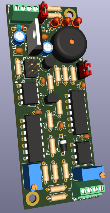
This was originally planned to be my first SMD project but the my brain put the electronics in the 'quite hard' pile, so possibly a step too far. Maybe. Even with THT the PCB is 32mm wide x 84mm tall so should be DIN rail mountable.
Attachments:
The following user(s) said Thank You: besriworld
Please Log in or Create an account to join the conversation.
- fletch
-
Topic Author
- Offline
- Premium Member
-
Less
More
- Posts: 140
- Thank you received: 71
20 Jan 2024 16:08 - 20 Jan 2024 16:17 #291208
by fletch
Replied by fletch on topic Probe Interface Board Design (resistance switching)
Well, that's depressing. My 21 year old Renishaw TP6 has given up the ghost. It was always a little dodgy on one of the 3 lobes but now it seems to have given up permanently. I think the internal spring mechanism was broken when I bought it as turning the adjust screw never changed the tension.The errant lobe never moved as far as the other two so possibly something has moved (again) inside.
Anyone ever disassembled one?
Ho hum

Edit: @Mecanix - Any chance of buying one of your spares?
Anyone ever disassembled one?
Ho hum
Edit: @Mecanix - Any chance of buying one of your spares?
Last edit: 20 Jan 2024 16:17 by fletch.
Please Log in or Create an account to join the conversation.
- andypugh
-

- Offline
- Moderator
-
Less
More
- Posts: 19871
- Thank you received: 4640
20 Jan 2024 16:49 #291212
by andypugh
Replied by andypugh on topic Probe Interface Board Design (resistance switching)
Late to the party....
I have a Renshaw MP3 that I bought from eBay a long time ago )because on eBay "Renshaw" probes go for lower prices than "Renishaw"
I once pressed tool release, with it in the spindle, so did get to see inside. At least with the MP3 there is nothing at all unusual in there, just the 6 balls and 3 bars that you would expect. It also had an inductive interface (just a coil that got connected / opened out by the probe contacts) that I never bothered to set up, instead I made a home-made magsafe connector and used it as a simple switch.
I then found half a dozen Zeiss CMM probes in a skip, and used those for a while (the MP3 was way oversized for my mill). These have an alternative to the Renishaw design, using rods rather than balls, of which more later.
These also have a piezo elemement in them, with the contacts being, presumably, a failsafe. I used these for a few years, but not with the piezo part, just as a conventional probe.
Another feature of these is that they have a parallel (and maybe series? I have forgotten) and series resistor, so that the restance changes, rather than going open-circuit. I wired them to a little interface circuit with a comparator on it to convert to digital output for LinuxCNC. I think that the parallel resistor probably prevents arcing, it feels like it should?
But I was intrugued by the design using rods, as it means that aslong as the _axis_ of the drillings is in the right place, the position of the rods is unimportant. And it's easier to solder to a rod too.
To investigate the robustmess of this design to machining inaccuracies, I made one using only a collet block and a drill press. And it worked farily well. If you make and assemble the body first, and add a screw to clamp it solid you can machine and drill the stylus mount hole into the pre-assembled body, and should get decent accuracy regardless of the internal accuracy.
I made two videos about this, one minimal-tools version, and one using all the fancy tools.
The following user(s) said Thank You: JohnnyCNC, fletch
Please Log in or Create an account to join the conversation.
- fletch
-
Topic Author
- Offline
- Premium Member
-
Less
More
- Posts: 140
- Thank you received: 71
20 Jan 2024 17:35 - 20 Jan 2024 17:45 #291213
by fletch
Replied by fletch on topic Probe Interface Board Design (resistance switching)
Oh wow, Andy - that is just such a beautifully simple design! Just eight parts (excluding the stylus & wiring).
I feel a 3D printed version is on the cards so I can continue developing the interface board. It will be interesting to see the difference in contact resistance compared to the Renishaw (or even Renshaw) ebay not-so-much-of-a-bargain. For the 3D printed one, I'll be using some chrome plated brass rod I happen to have lying around.
The piezo is curious - I would have expected that to be used for some kind of resistance measuring?
Thanks for the hints on order of operations (especially the drilling of the stylus hole) - and for the great videos, including the vice tightening! Morale has been duly lifted.
Philip
Last edit: 20 Jan 2024 17:45 by fletch. Reason: Dodgy moral(s). E lad.
Please Log in or Create an account to join the conversation.
Moderators: PCW, jmelson
Time to create page: 0.213 seconds