Light Machine Corp. Benchman XTr (retrofit)
- steve_a
- Offline
- Senior Member
-

Less
More
- Posts: 75
- Thank you received: 2
14 Jul 2016 23:00 - 16 Jul 2016 00:01 #77469
by steve_a
Replied by steve_a on topic Light Machine Corp. Benchman XTr (retrofit)
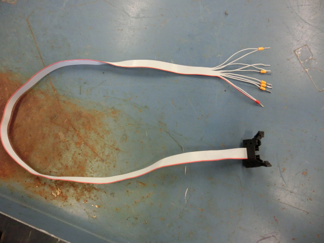
Encoders: As I mentioned I a made a couple of cables that plug into the Encoder ribbon cables... This seems to be working well. On the BenchmanXT, So far I know that the X and Y axis are 50,000 counts/inch. A LOT of resolution and I seem to be getting really good accuracy. It HAS been unloaded so far but I'm hoping for really good results. My target is no more than .0005" error.
Here's my breakout from the encoders. My X cable has different colors but the signals still appear on the same ribbon cable conductors.
Encoder Output , Ribbon Cable , Ribbon Cable Conductor
VCC +5V White > Brown > 1
( VCC +5 White) > White > 2
- B channel Blue > Red > 3
+ B channel Green > White > 4
- A channel Pink > Orange > 5
+ A channel Red > White > 6
+ Z channel Yellow > Yellow > 7
0 V (grn) Black > White > 8
- Z channel Orange > Green > 9
( 0 V (grn) Black) > White > 10
Last edit: 16 Jul 2016 00:01 by steve_a. Reason: Add photos
Please Log in or Create an account to join the conversation.
- steve_a
- Offline
- Senior Member
-
Less
More
- Posts: 75
- Thank you received: 2
26 Jul 2016 15:56 #78047
by steve_a
Replied by steve_a on topic Light Machine Corp. Benchman XTr (retrofit)
So, FYI. use caution when enabling the machine. If there is a signal present and you have the encoder connected to tell the machine where the axis currently sits... and it doesn't match the target. It will react according to the PID settings and could run wild. I strongly advise anyone replacing the controller, to use a temporary extra emergency stop button for test purposes, that feeds the grounds (from pin 2) to the the Enable (pin 11), POS Enable (pin12) and NEG Enable (pin 13) on the amplifiers. This will allow you to disable everything quickly in case something unexpected happens and prevent breaking anything on the drive system. Oh and another FYI... you can get replacement drive belts from McMaster Carr: item number 6484K219 XL Series Timing Belt, Trade No. 90XL037.
Please Log in or Create an account to join the conversation.
- PCW
-

- Offline
- Moderator
-

Less
More
- Posts: 17927
- Thank you received: 5251
26 Jul 2016 16:34 #78049
by PCW
Replied by PCW on topic Light Machine Corp. Benchman XTr (retrofit)
Having Linuxcnc in control of the drive enables is really one of the first things that should be done in a servo retrofit
as this will catch runaways much faster than you can hit Estop (Estop is of course still needed)
If the encoders are working and LinuxCNC has control of the drive enables, you will get an immediate following error
and disabled drives in the event of a runaway
as this will catch runaways much faster than you can hit Estop (Estop is of course still needed)
If the encoders are working and LinuxCNC has control of the drive enables, you will get an immediate following error
and disabled drives in the event of a runaway
Please Log in or Create an account to join the conversation.
- steve_a
- Offline
- Senior Member
-
Less
More
- Posts: 75
- Thank you received: 2
27 Jul 2016 14:26 #78071
by steve_a
Replied by steve_a on topic Light Machine Corp. Benchman XTr (retrofit)
You are correct... I have a a bunch of wires strung all over the place just to test and be sure I know how I want to wire this thing. I've got pretty basic control just yet so I'm walking a tightrope for the moment. I'm just giving as much information as I can for anyone crazy enough to do the same. I'll have it under better control soon.
Please Log in or Create an account to join the conversation.
- MacGalempsy
- Offline
- Senior Member
-
Less
More
- Posts: 68
- Thank you received: 2
28 Jul 2016 01:03 #78085
by MacGalempsy
Replied by MacGalempsy on topic Light Machine Corp. Benchman XTr (retrofit)
Just an update on the original post. The machine made its first controlled cuts! The only things swapped were the oem mainboards for Mesa 5i25, 7i77 & 7i84. Only things added were a few pullup resistors and quiteva few relays!
WORKING
- X.Y, and Z axes home and move within 0.0002"
- zbrake off when estop is out
- spindle runs at variable speed
- flood coolant
- renishaw touch probe in (need to make a bracket for the tool height setter)
- ATC: actuators, endstops, dc motor, atc encoder, spindle hall detector
- electro doorlock signals closed and locked
- light comes on
- sso & fro pots input read (resds voltage in)
To-Do List
- setup classic ladder for the ATC
- figure out how to use the probe interface
- set scales on sso snd fro for pot adjustments
- interface physical on/off button
- setup mpg and increment dials
- machine new atc collet holders to work with Darkon collets
- setup 4th axis
The thing that made it all start to click was rearranging a copy of the hal file into components, parameters, and signals/pins.
Please Log in or Create an account to join the conversation.
- BigJohnT
-

- Offline
- Administrator
-

Less
More
- Posts: 3990
- Thank you received: 994
30 Jul 2016 23:20 #78175
by BigJohnT
Replied by BigJohnT on topic Light Machine Corp. Benchman XTr (retrofit)
If you need help with classicladder holler.
I used classicladder for my Hardinge CHNC turret gnipsel.com/shop/hardinge/hardinge.xhtml
I also have a turret sim gnipsel.com/files/linuxcnc/configs/cl-turret-sim.zip
and a classicladder tutorial gnipsel.com/linuxcnc/ladder/index.html
Looking Good!
JT
I used classicladder for my Hardinge CHNC turret gnipsel.com/shop/hardinge/hardinge.xhtml
I also have a turret sim gnipsel.com/files/linuxcnc/configs/cl-turret-sim.zip
and a classicladder tutorial gnipsel.com/linuxcnc/ladder/index.html
Looking Good!
JT
The following user(s) said Thank You: MacGalempsy
Please Log in or Create an account to join the conversation.
- Muzzer
- Offline
- Elite Member
-

Less
More
- Posts: 266
- Thank you received: 42
31 Jul 2016 11:44 - 31 Jul 2016 11:46 #78179
by Muzzer
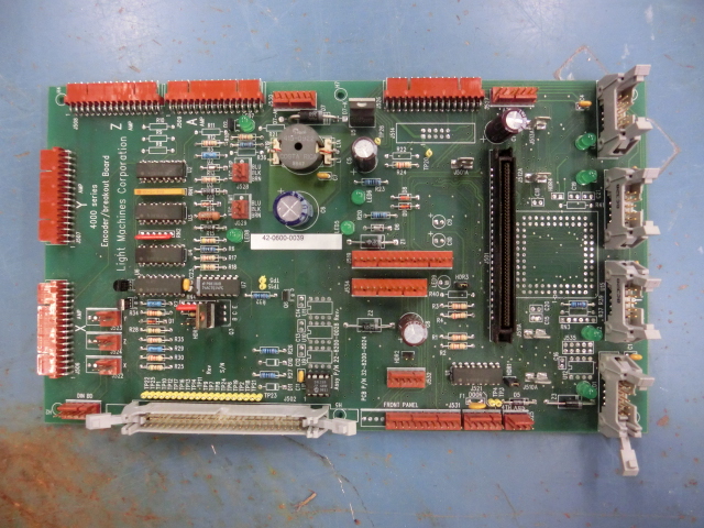
The encoder in the motors is a Tamagawa "Singlesyn" or "Smartsyn" resolver that can't be used without the dedicated ASIC (also made by Tamagawa). It's a funny magnetic component with an "exciter" winding (Z) and 2 outputs A & B. The ASIC drives the resolver Z winding with a high frequency waveform and also does lots of processing on the resulting output signals. Several outputs are available including the simple pulse output that is used here. For permanent magnet motors where rotor position information is critical etc, it provides a 10 / 12 bit absolute position signal and that's normally why people install them. Seems a bit of overkill just to generate a speed / direction signal but it's a very good quality solution.
Basically, if you want to use this original (absolute position) encoder you will need to retain the interface board with its ASIC (AU6802). If you want a simpler solution, you may be better off removing the encoder and associated interface board and replacing them with a much simpler and conventional (speed) encoder.
Replied by Muzzer on topic Light Machine Corp. Benchman XTr (retrofit)
So on my ProLight (which I think is pretty much the same machine) there's a board that takes the encoders as an input and runs through several logic chips to produce a tachometer output. At one point I tried tracing out all of these components and found datasheets for them and got a schematic but if I remember correctly I would have needed a few more supply voltages then just +5 and +24. I think each of the LED's below and to the left of this tachometer board correspond to each of these supply voltages which are fed from the box that houses the computer. I ended up just getting rid of that board and running the servos in torque mode and have been happy with it. I can look up the tuning values that I used if you want.
-Shawn
The encoder in the motors is a Tamagawa "Singlesyn" or "Smartsyn" resolver that can't be used without the dedicated ASIC (also made by Tamagawa). It's a funny magnetic component with an "exciter" winding (Z) and 2 outputs A & B. The ASIC drives the resolver Z winding with a high frequency waveform and also does lots of processing on the resulting output signals. Several outputs are available including the simple pulse output that is used here. For permanent magnet motors where rotor position information is critical etc, it provides a 10 / 12 bit absolute position signal and that's normally why people install them. Seems a bit of overkill just to generate a speed / direction signal but it's a very good quality solution.
Basically, if you want to use this original (absolute position) encoder you will need to retain the interface board with its ASIC (AU6802). If you want a simpler solution, you may be better off removing the encoder and associated interface board and replacing them with a much simpler and conventional (speed) encoder.
Last edit: 31 Jul 2016 11:46 by Muzzer. Reason: Unauthorised emoticon
Please Log in or Create an account to join the conversation.
- andypugh
-

- Offline
- Moderator
-
Less
More
- Posts: 19863
- Thank you received: 4636
31 Jul 2016 17:22 - 31 Jul 2016 17:24 #78195
by andypugh
Mesa offer a board that works _very_ nicely with resolvers.
Mesa 7i49
I like it so much that on my recent Lathe retrofit I removed an encoder and fitted a resolver")
The 7i49 produces a very high quality velocity output, and it would be relatively easy to route that back to one of the analogue outputs on the board to get a velocity-proportional voltage.
Replied by andypugh on topic Light Machine Corp. Benchman XTr (retrofit)
Basically, if you want to use this original (absolute position) encoder you will need to retain the interface board with its ASIC (AU6802). If you want a simpler solution, you may be better off removing the encoder and associated interface board and replacing them with a much simpler and conventional (speed) encoder.
Mesa offer a board that works _very_ nicely with resolvers.
Mesa 7i49
I like it so much that on my recent Lathe retrofit I removed an encoder and fitted a resolver
The 7i49 produces a very high quality velocity output, and it would be relatively easy to route that back to one of the analogue outputs on the board to get a velocity-proportional voltage.
Last edit: 31 Jul 2016 17:24 by andypugh.
Please Log in or Create an account to join the conversation.
- BigJohnT
-
- Offline
- Administrator
-
Less
More
- Posts: 3990
- Thank you received: 994
31 Jul 2016 21:08 #78209
by BigJohnT
Replied by BigJohnT on topic Light Machine Corp. Benchman XTr (retrofit)
Please Log in or Create an account to join the conversation.
- steve_a
- Offline
- Senior Member
-
Less
More
- Posts: 75
- Thank you received: 2
01 Aug 2016 23:49 #78263
by steve_a
Replied by steve_a on topic Light Machine Corp. Benchman XTr (retrofit)
Before I tear into the Z axis, does anyone know how to adjust the Z axis on a Benchman? My unit is so loose that when the brake is deactivated the head just travels down on its own. This is a problem because the servo spikes on a downward move at about .006" error for a very short time before it corrects. I'm thinking I need to either counterbalance the Z axis or tighten the gibs to reduce the amount of "shock" from gravity. Any input would be appreciate.
Please Log in or Create an account to join the conversation.
Time to create page: 0.465 seconds