Fryer MB-11 Bed Mill Retrofit
- PCW
-

- Offline
- Moderator
-

Less
More
- Posts: 17977
- Thank you received: 5275
05 Jul 2018 18:48 #113493
by PCW
Replied by PCW on topic Fryer MB-11 Bed Mill Retrofit
Another option is to use a 7I90 in sserial remote mode
This would give you 72 I/O pins if you have a free sserial port available.
These I/Os can drive LEDs but best in sinking mode (LED anode to +5V through current limit resistor)
This would give you 72 I/O pins if you have a free sserial port available.
These I/Os can drive LEDs but best in sinking mode (LED anode to +5V through current limit resistor)
Please Log in or Create an account to join the conversation.
- adamj12b
-
 Topic Author
- Offline
- Senior Member
-

Less
More
- Posts: 45
- Thank you received: 5
05 Jul 2018 18:59 #113498
by adamj12b
Replied by adamj12b on topic Fryer MB-11 Bed Mill Retrofit
Type in the past thread. I already plan to use a 7i73 in the console so that I can use the matrix keypad for the 43 keys. If there was an esy way to shrink the matrix to 6x8 from 8x8, I would have enough outputs.
I think im going to experiment with the shift registers as that seems to be the only thing that makes sense currently. It doesn't make sense cost or wiring wise to add another mesa board to drive led's...
-Adam
I think im going to experiment with the shift registers as that seems to be the only thing that makes sense currently. It doesn't make sense cost or wiring wise to add another mesa board to drive led's...
-Adam
Please Log in or Create an account to join the conversation.
- DeckelHead
- Offline
- Elite Member
-

Less
More
- Posts: 166
- Thank you received: 2
05 Jul 2018 20:24 - 06 Jul 2018 14:18 #113512
by DeckelHead
Replied by DeckelHead on topic Fryer MB-11 Bed Mill Retrofit
Adam... I'm not sure I understand what you are asking... Are you looking for an explanation of how shift registers work or do you have a question regarding that specific wiki?
As far as the engraving issues go... I only have a very old version of Illustrator, and that seems to crash whenever I import the file for my panel. I'll have to get the other application (as I recall, that is an open source one), but I'm very green on how to use these so it will take me a bit of work. The alternate approach is Andy's, and because that is all inside Fusion, it will probably be my first attempt. I seem to grapple with constraints in the app though.
I had a devil of a time doing something that should have been pretty easy (essentially ensuring that two cutouts where equidistant, both horizontally and vertically, between three columns of (mounting) holes). In AutoCAD (or Draftsight, which is what I've moved to), this would have taken me no time at all. But in Fusion, I have a devil of a time. Of course, I don't dispute that Fusion's parametric is better. I can change one of those holes and everything rescales appropriately. But learning the tricks of constraints has been a bit difficult. I've also found that my components tend to disappear and the timeline goes way back in time periodically and I don't know why. I also seem to have a difficult time copying items. I don't get any error messages, but the copied items never show up. Puzzling.
It is all a learning exercise, and eventually I know it will click. That doesn't mean that it isn't frustrating sometimes though.")
Anyhow, thank you for the suggestions on how to handle engraving. Those give me a fighting chance. What is the exact definition of v-carving though? Is it the replication of a variable depth Vee, such as you would have when you manually carve art?
As far as the engraving issues go... I only have a very old version of Illustrator, and that seems to crash whenever I import the file for my panel.
I'll have to get the other application (as I recall, that is an open source one), but I'm very green on how to use these so it will take me a bit of work. The alternate approach is Andy's, and because that is all inside Fusion, it will probably be my first attempt. I seem to grapple with constraints in the app though.I had a devil of a time doing something that should have been pretty easy (essentially ensuring that two cutouts where equidistant, both horizontally and vertically, between three columns of (mounting) holes). In AutoCAD (or Draftsight, which is what I've moved to), this would have taken me no time at all. But in Fusion, I have a devil of a time. Of course, I don't dispute that Fusion's parametric is better. I can change one of those holes and everything rescales appropriately. But learning the tricks of constraints has been a bit difficult. I've also found that my components tend to disappear and the timeline goes way back in time periodically and I don't know why. I also seem to have a difficult time copying items. I don't get any error messages, but the copied items never show up. Puzzling.
It is all a learning exercise, and eventually I know it will click. That doesn't mean that it isn't frustrating sometimes though.
Anyhow, thank you for the suggestions on how to handle engraving. Those give me a fighting chance.
What is the exact definition of v-carving though? Is it the replication of a variable depth Vee, such as you would have when you manually carve art?
Last edit: 06 Jul 2018 14:18 by DeckelHead.
Please Log in or Create an account to join the conversation.
- DeckelHead
- Offline
- Elite Member
-
Less
More
- Posts: 166
- Thank you received: 2
07 Jul 2018 20:52 - 07 Jul 2018 20:53 #113719
by DeckelHead
Replied by DeckelHead on topic Fryer MB-11 Bed Mill Retrofit
(this comment relates to Andy's thoughts about using a diagonal line to position engraving text within F360)
Seems like there is one slight problem with this approach. The box is a function of the leading. So, Those that have a character, such as 'g', that go below the baseline, will have a midpoint of the diagonal line that is lower than those words like 'Start' that have no descenders. That means that 'Engraving' will be positioned lower than Start.
Seems like there is one slight problem with this approach. The box is a function of the leading. So, Those that have a character, such as 'g', that go below the baseline, will have a midpoint of the diagonal line that is lower than those words like 'Start' that have no descenders. That means that 'Engraving' will be positioned lower than Start.
Last edit: 07 Jul 2018 20:53 by DeckelHead.
Please Log in or Create an account to join the conversation.
- andypugh
-

- Offline
- Moderator
-
Less
More
- Posts: 19875
- Thank you received: 4642
07 Jul 2018 21:28 #113725
by andypugh
The new items might be exactly on top of the original.
Replied by andypugh on topic Fryer MB-11 Bed Mill Retrofit
I also seem to have a difficult time copying items. I don't get any error messages, but the copied items never show up.
The new items might be exactly on top of the original.
Please Log in or Create an account to join the conversation.
- andypugh
-
- Offline
- Moderator
-
Less
More
- Posts: 19875
- Thank you received: 4642
07 Jul 2018 21:44 #113727
by andypugh
Replied by andypugh on topic Fryer MB-11 Bed Mill Retrofit
This might help
forums.autodesk.com/t5/fusion-360-design...t-issue/td-p/7447998
But also seems to confirm that text positioning is a bit messed-up in Fusion.
forums.autodesk.com/t5/fusion-360-design...t-issue/td-p/7447998
But also seems to confirm that text positioning is a bit messed-up in Fusion.
Please Log in or Create an account to join the conversation.
- adamj12b
-
Topic Author
- Offline
- Senior Member
-
Less
More
- Posts: 45
- Thank you received: 5
11 Jul 2018 18:50 #114020
by adamj12b
Replied by adamj12b on topic Fryer MB-11 Bed Mill Retrofit
I think I know the answer, but I have added some features to the mill and need to control them.
One of them is a chip auger. I have this set up with a current sensing relay and a set of reversing relays.
The theory of operation would be to activate output 1 for auger forward, using a custom M131. Auger reverse (M132) should activate output 1 and output 2 to run the auger and activate the reversing relay. M133 would stop all auger motion.
When the auger is running, an input from the current relay would signal a jam and the auger should switch direction for a programmed amount of time and then revert to previous running direction. If this happens 3 times in a row, the system should throw a error on the screen, and shut off the auger.
My thought was that this needs to be programmed in Classic Ladder. Does this seem correct? Is there some other scripting language in the system that would suit this better?
The second thing im implementing is a float sensor in the pan of the machine. The way everything worked out, I ended up with a coolant tank larger then the capacity of the chip tray. I do not want to flood the shop with coolant so a float in the pan will handle this well. I want to have this set up to feed hold the machine and put a warning on the screen stating a coolant backup. What would be the best way to do this?
-Adam
Please Log in or Create an account to join the conversation.
- andypugh
-
- Offline
- Moderator
-
Less
More
- Posts: 19875
- Thank you received: 4642
11 Jul 2018 18:56 #114021
by andypugh
You could program is in C as a custom HAL component:
linuxcnc.org/docs/2.7/html/hal/comp.html
Or seeing as it doesn't really need real-time you could use a Python component:
linuxcnc.org/docs/2.7/html/hal/halmodule.html
Replied by andypugh on topic Fryer MB-11 Bed Mill Retrofit
My thought was that this needs to be programmed in Classic Ladder. Does this seem correct? Is there some other scripting language in the system that would suit this better?
You could program is in C as a custom HAL component:
linuxcnc.org/docs/2.7/html/hal/comp.html
Or seeing as it doesn't really need real-time you could use a Python component:
linuxcnc.org/docs/2.7/html/hal/halmodule.html
Please Log in or Create an account to join the conversation.
- adamj12b
-
Topic Author
- Offline
- Senior Member
-
Less
More
- Posts: 45
- Thank you received: 5
21 Nov 2019 18:24 #150852
by adamj12b
Replied by adamj12b on topic Fryer MB-11 Bed Mill Retrofit
So its been a bit over a year since a major update.
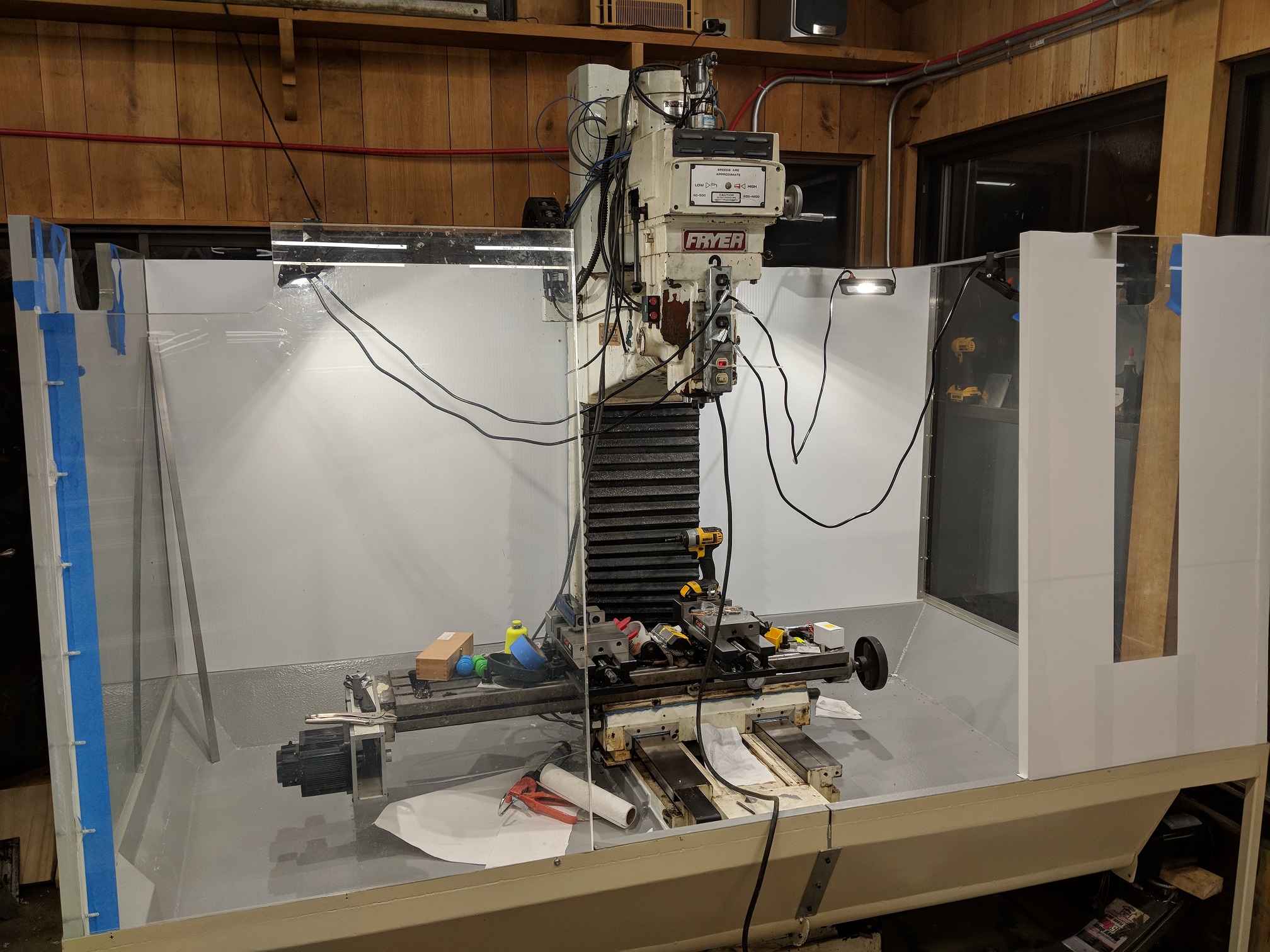
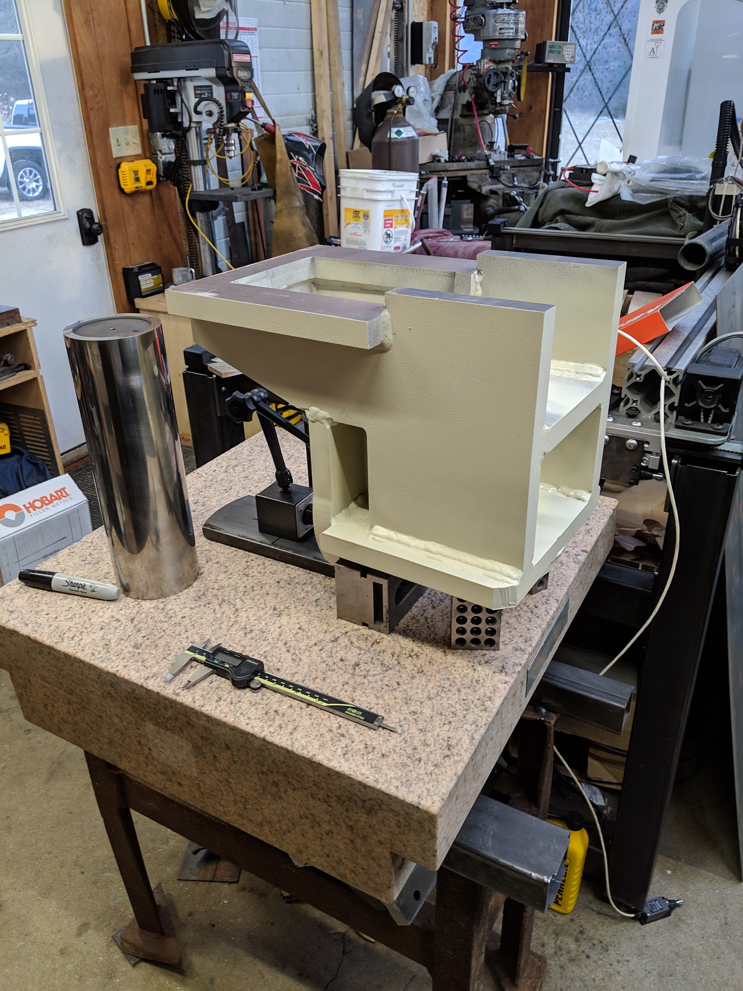
Last year I enclosed the whole machine, building a chip pan out of hot rolled sheet and welding all the seams. This was then painted to match the mill and the inside painted with epoxy. The walls were constructed by 1.25" lexan sheets that were left at my new house by the previous owner(hoarder). They made for one solid enclosure that nothing is going to come through. I was able to get the coolant plumbed and finally had the machine at a working capacity.
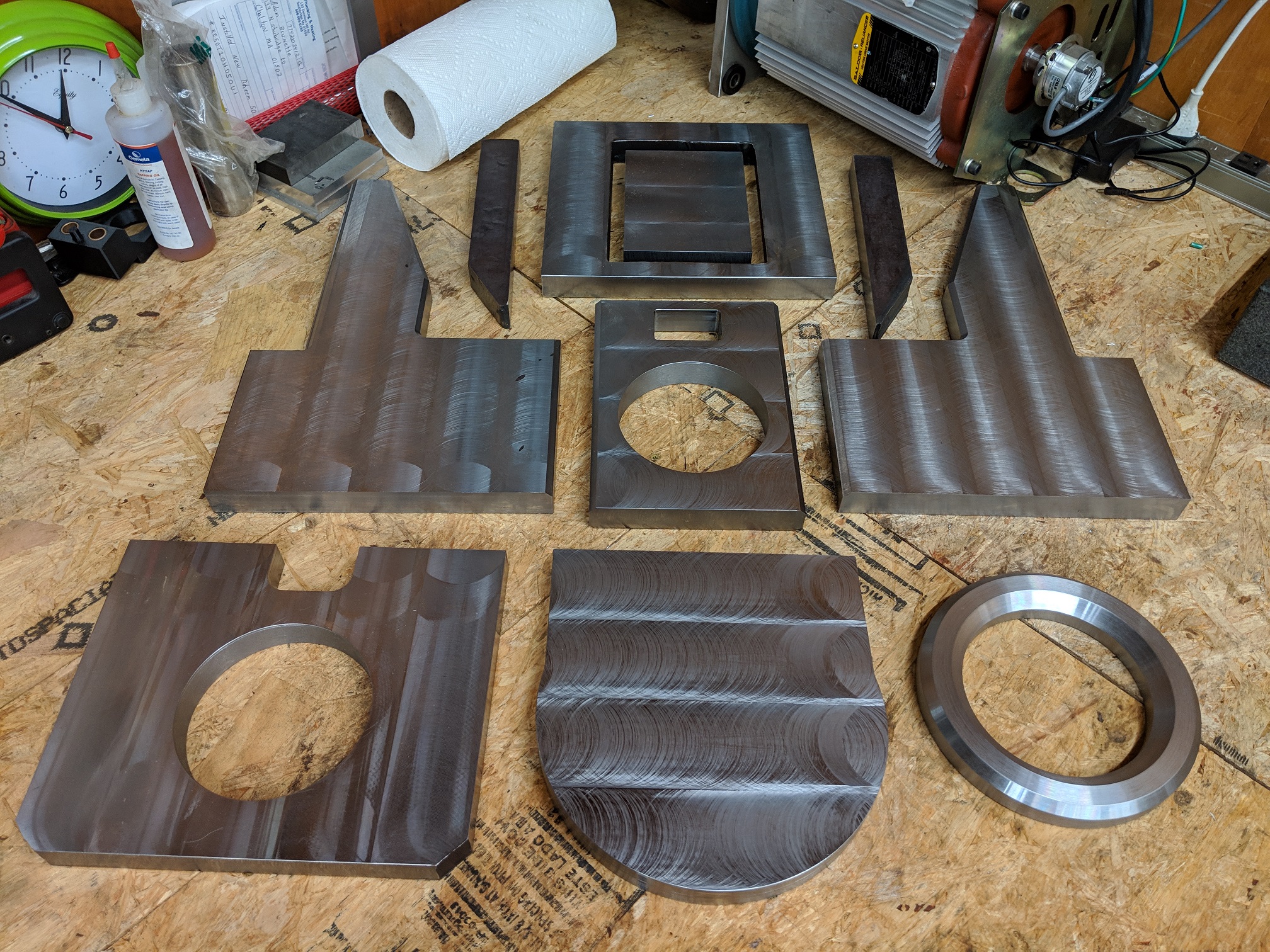
In the winter of 2019, I started work on my biggest single piece yet. I had purchased a Brand new 2017 Haas Mini Mill spindle head. This was the casting, motor, spindle cartridge and tool release piston. I spent considerable time towards the end of 2018 measuring the Fryers existing head assembly and the Haas head, and designed a custom weldment to fabricate a new head for the mill, using the Haas components.
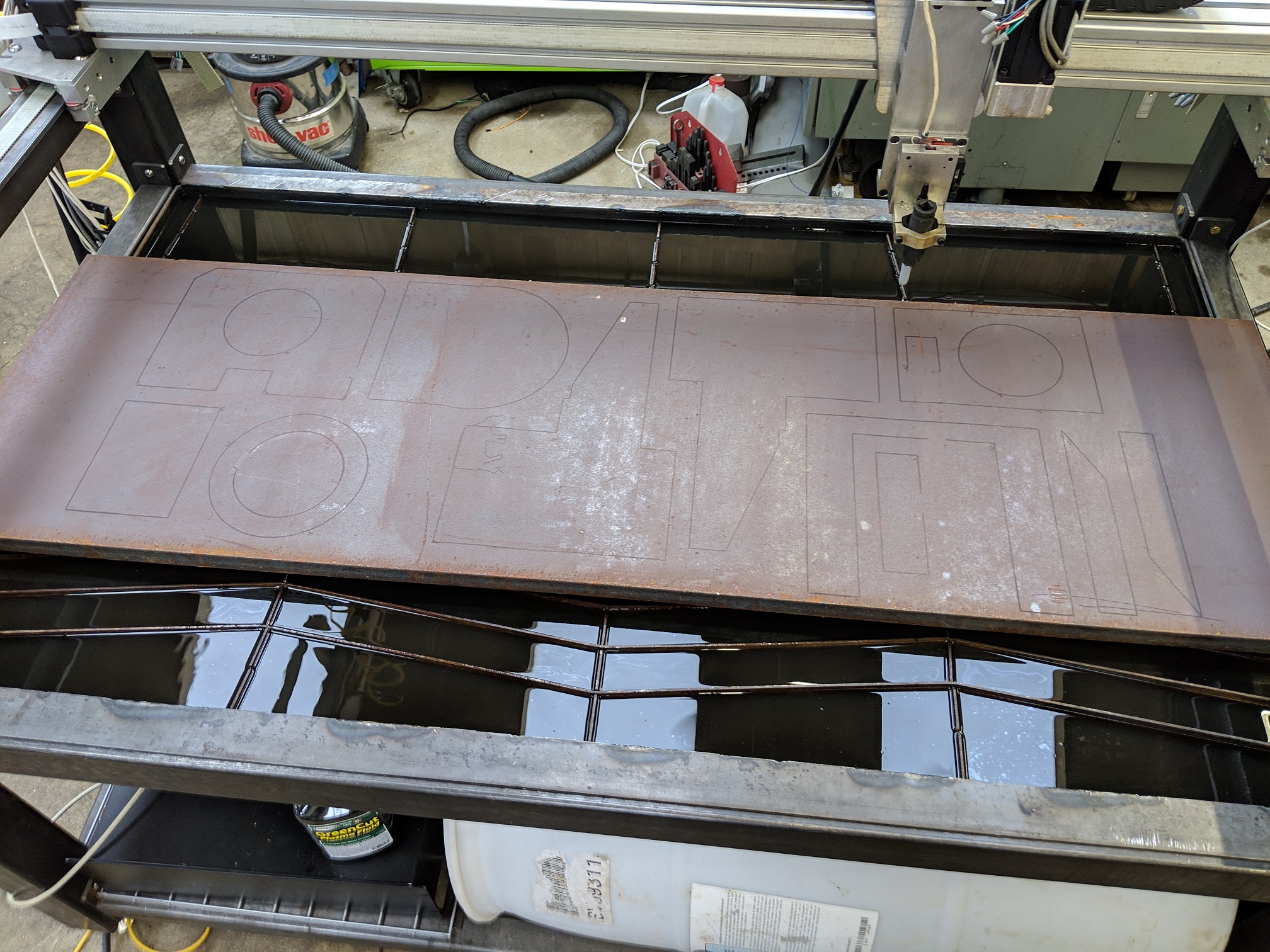
All the pieces of the weldment were cut from 1" A36 steel on the plasma table. In hindsight this was a mistake. Due to the thickness and the 80A plasma unit being under powered for this thickness, I would have been better off having the parts cut on a water jet so the heat effected zone was not so large and the kerf as well... Lesson leaned. I finished machined all the parts and cut bevels on all mating edges to prepare for welding.
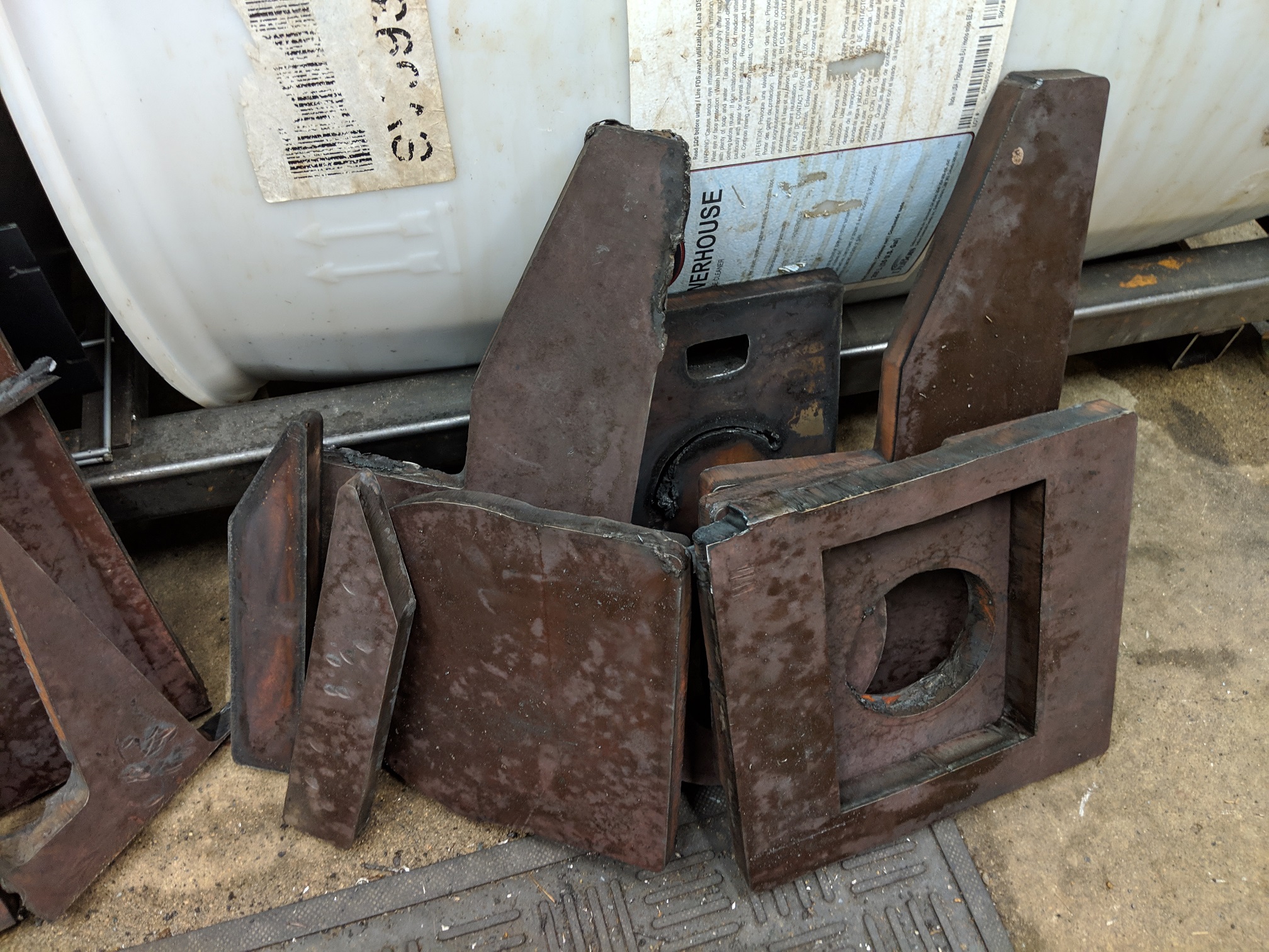
Welding was done with a 255A Lincoln Mig machine running Hobart 0.047 Tripple 7 dual shield wire. After this was complete, I sent the weldment to heat treat for stress relieving before final machining.
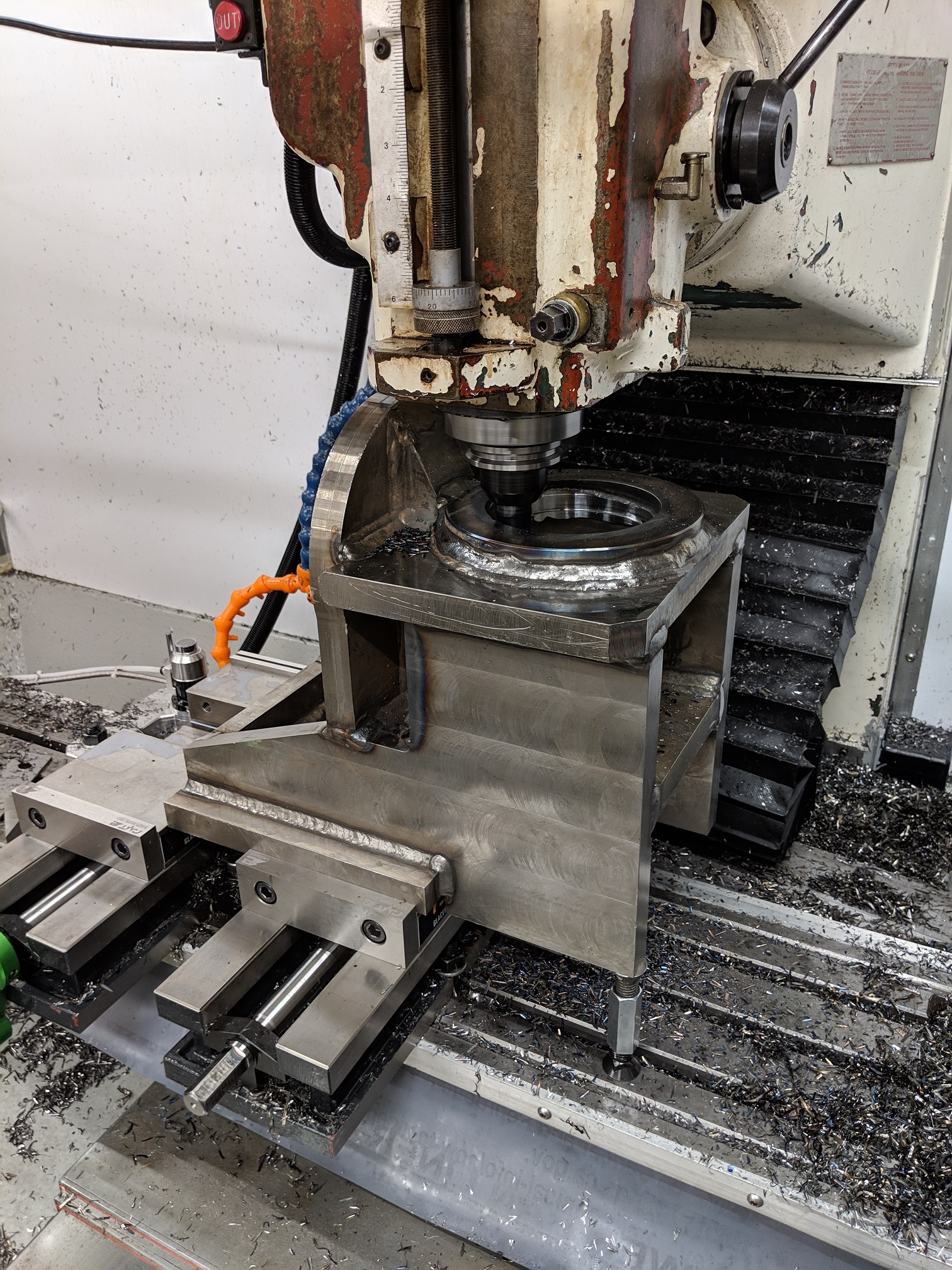
Once final machining was done, I was able to do a rough assembly and weigh the new assembly and find the difference in weight between the new head and the old one. This machine has a cast iron counter weight in the column for the head. I was unable to remove this for trimming, so I had to add mass to the head itself to balance out. I ended up designing a lead weight that I ended up casting 2 of, to bolt to the sides of the head under the shroud to add the required 40lbs of mass that was needed.
Ive been using the new spindle for 7 months now and am very happy with it. I increased RPM, gained rigid tapping and orientation and ended up with much lower run out and lower running temp.
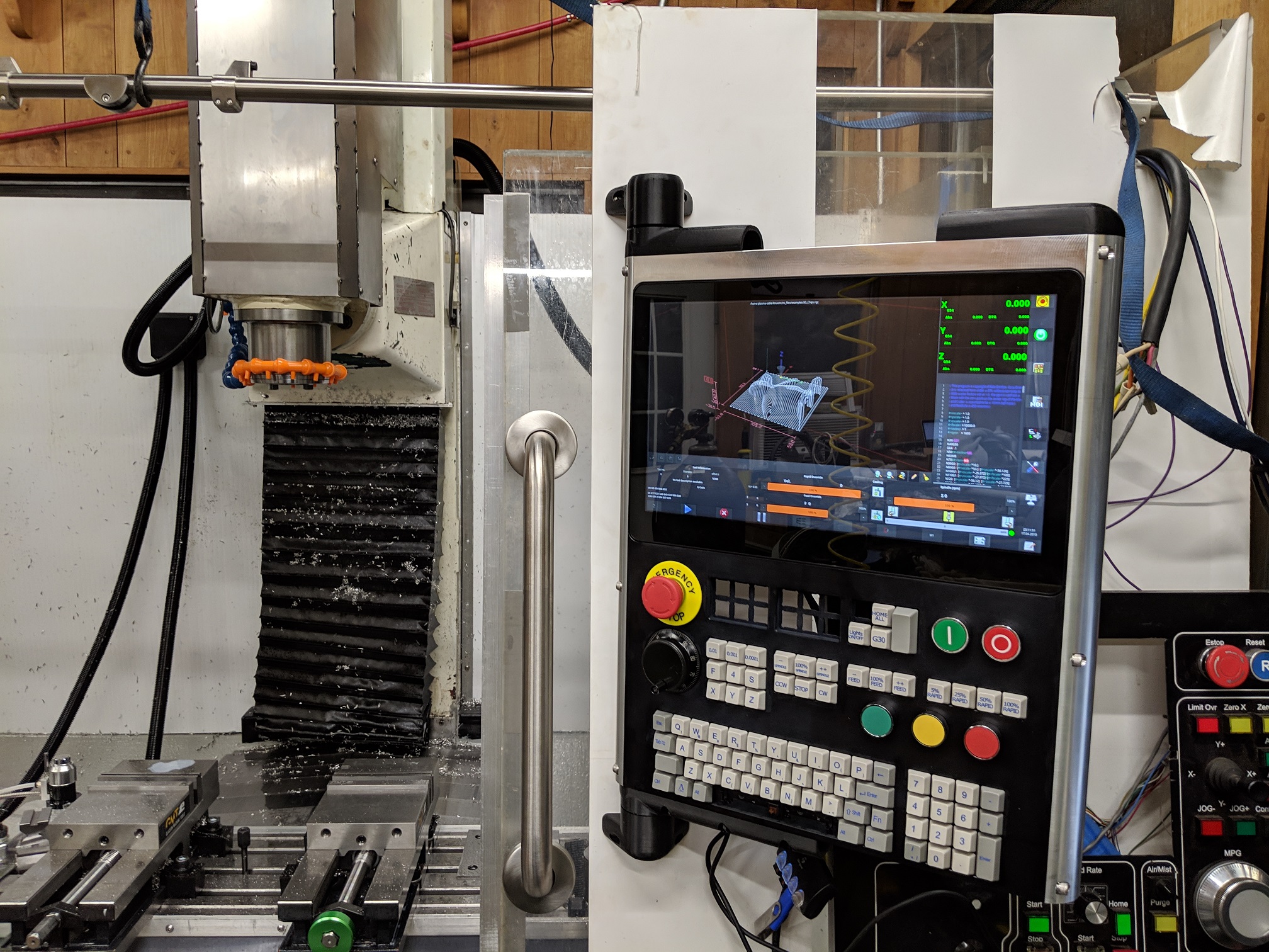
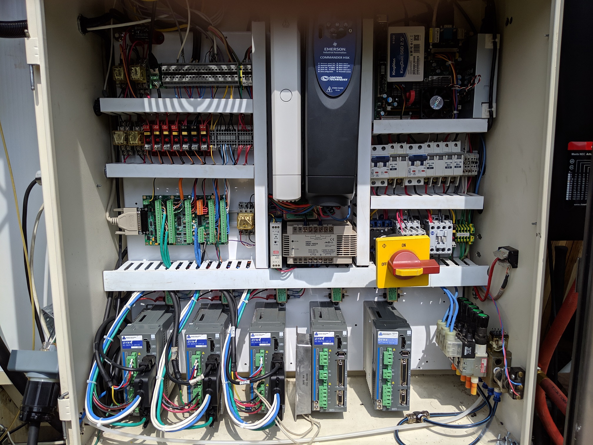
I spent some time this summer adjusting little wiring things and working on my console design. Here are some pics of how the machine sits now.
I have started working on a harmonic 4th axis which I will be adding a perpendicular harmonic drive to to form a trunion for full 5 axis capability. Ill post an update about that soon.
Check out the google album on the first post of this thread for more pictures.
-Adam
Last year I enclosed the whole machine, building a chip pan out of hot rolled sheet and welding all the seams. This was then painted to match the mill and the inside painted with epoxy. The walls were constructed by 1.25" lexan sheets that were left at my new house by the previous owner(hoarder). They made for one solid enclosure that nothing is going to come through. I was able to get the coolant plumbed and finally had the machine at a working capacity.
In the winter of 2019, I started work on my biggest single piece yet. I had purchased a Brand new 2017 Haas Mini Mill spindle head. This was the casting, motor, spindle cartridge and tool release piston. I spent considerable time towards the end of 2018 measuring the Fryers existing head assembly and the Haas head, and designed a custom weldment to fabricate a new head for the mill, using the Haas components.
All the pieces of the weldment were cut from 1" A36 steel on the plasma table. In hindsight this was a mistake. Due to the thickness and the 80A plasma unit being under powered for this thickness, I would have been better off having the parts cut on a water jet so the heat effected zone was not so large and the kerf as well... Lesson leaned. I finished machined all the parts and cut bevels on all mating edges to prepare for welding.
Welding was done with a 255A Lincoln Mig machine running Hobart 0.047 Tripple 7 dual shield wire. After this was complete, I sent the weldment to heat treat for stress relieving before final machining.
Once final machining was done, I was able to do a rough assembly and weigh the new assembly and find the difference in weight between the new head and the old one. This machine has a cast iron counter weight in the column for the head. I was unable to remove this for trimming, so I had to add mass to the head itself to balance out. I ended up designing a lead weight that I ended up casting 2 of, to bolt to the sides of the head under the shroud to add the required 40lbs of mass that was needed.
Ive been using the new spindle for 7 months now and am very happy with it. I increased RPM, gained rigid tapping and orientation and ended up with much lower run out and lower running temp.
I spent some time this summer adjusting little wiring things and working on my console design. Here are some pics of how the machine sits now.
I have started working on a harmonic 4th axis which I will be adding a perpendicular harmonic drive to to form a trunion for full 5 axis capability. Ill post an update about that soon.
Check out the google album on the first post of this thread for more pictures.
-Adam
The following user(s) said Thank You: tommylight
Please Log in or Create an account to join the conversation.
Time to create page: 0.392 seconds