what to do with a free scrap dumpster find ?
- machinedude
-
 Topic Author
- Offline
- Platinum Member
-

Less
More
- Posts: 715
- Thank you received: 312
04 Feb 2022 11:26 - 04 Feb 2022 11:27 #233963
by machinedude
Replied by machinedude on topic what to do with a free scrap dumpster find ?
The fans were sitting around and free. My oldest daughter built a gaming PC and bought a bulk lot of them since it was cheaper to buy them that way and used 1 so i had 4 of them sitting here for a while.
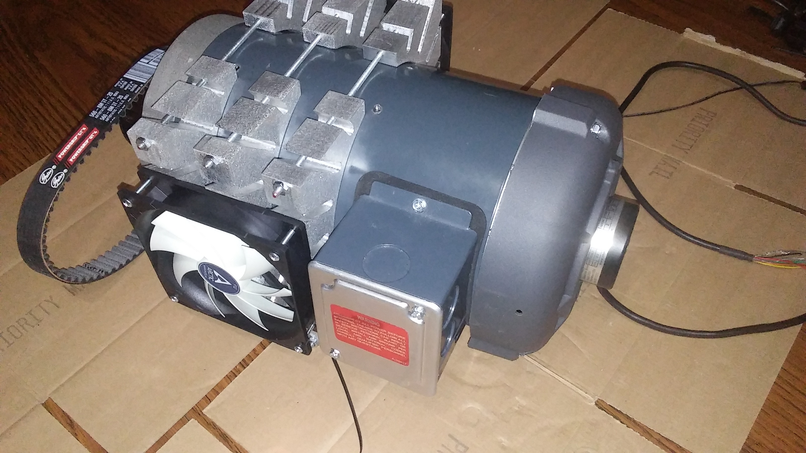
with this motor it was rated for constant torque from 345 RPM to 3450 RPM. the slower speeds is where the motor was lacking before with the original fan mounted to the motor shaft. at slower speeds below the rating you run the risk of getting the motor to hot and doing damage this should correct a lot of it i think. the rest of it falls back on the internal wiring and the gauge of wire being able to handle the loads at slower speeds. being an invertor duty motor that part is more robust than a standard 3 phase motor but i don't know how slow i can run it and keep it safe? the motor has plenty of torque so i don't think that would have any issue there since the rated torque is around 18 ft/lbs(24.4 Nm) and the breakdown torque is around 22 ft/lbs,
i looked at some induction motors with encoders and they were not cheap i remember seeing one over $3,000. this motor was retired and i got a deal on it so it was only $350 and the encoder was only $55 so i'm well under $500
servo motors can be had but i think the speeds are limited to around 3,000 RPM so by the time you gear them up to get 5,000 rpm to 6000 rpm you loose half the rated torque and the torque curve is already dropping off before you hit the rated speed on top of that.
running this motor at 90Hz will give me around 5,200 RMP which i feel is a safe limit since the encoder is rated at 6,000 RPM the motor should be safe at this range too, seems to be the normal for over speeding limits with a VFD. i don't know the torque curve for this set up but the drop off starts at above 3450 RPM and with 24.4 Nm of torque it has room for loss at high speeds.
this motor with the mods has a weight of around 50lbs so how much of a weight difference there is between a invertor duty motor and a servo motor in the same range is i don't know? i think a servo could be lighter but it can't be to drastic of a difference i would think?
Last edit: 04 Feb 2022 11:27 by machinedude.
Please Log in or Create an account to join the conversation.
- machinedude
-
Topic Author
- Offline
- Platinum Member
-
Less
More
- Posts: 715
- Thank you received: 312
05 Feb 2022 12:48 #234019
by machinedude
Replied by machinedude on topic what to do with a free scrap dumpster find ?
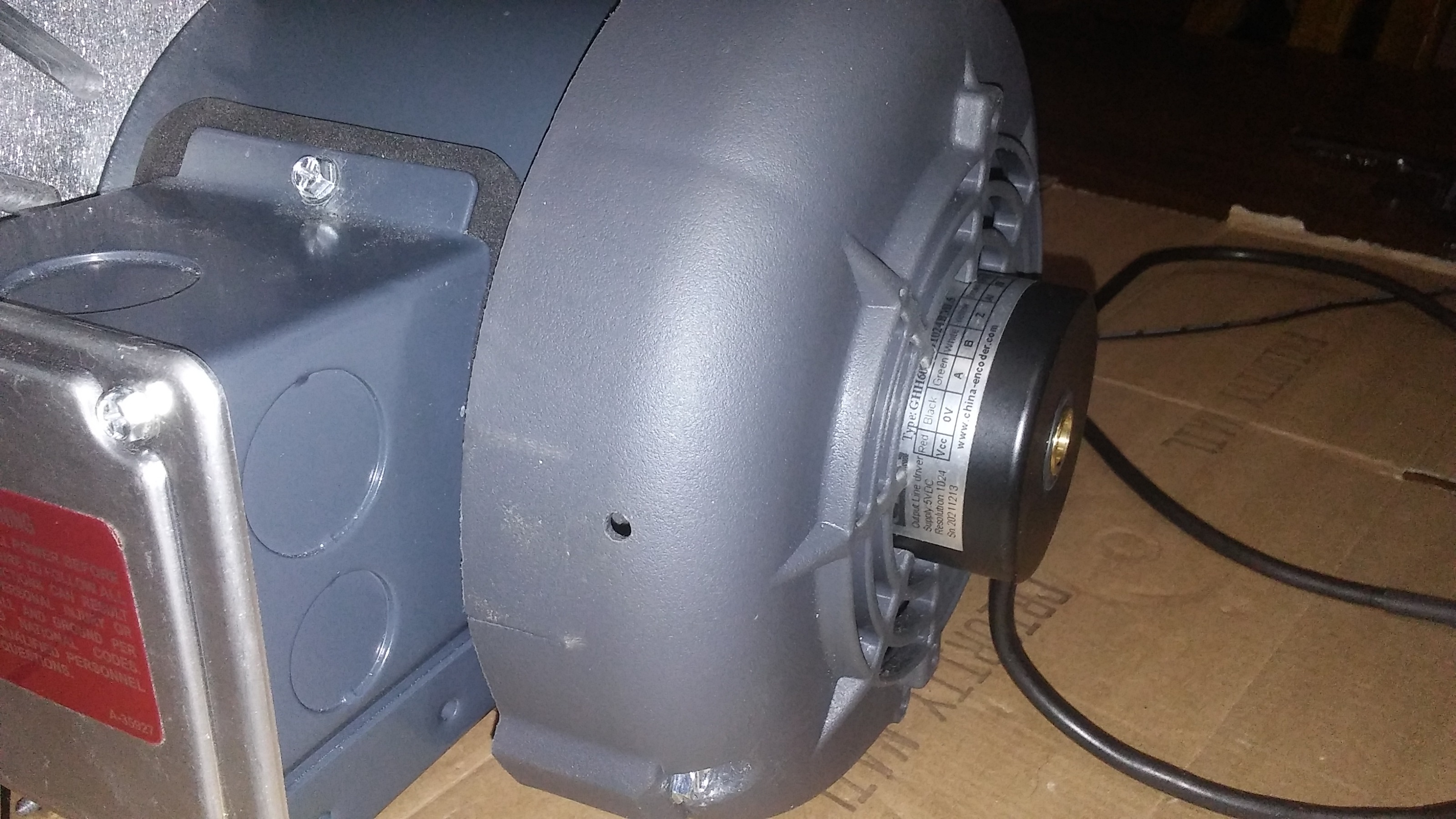
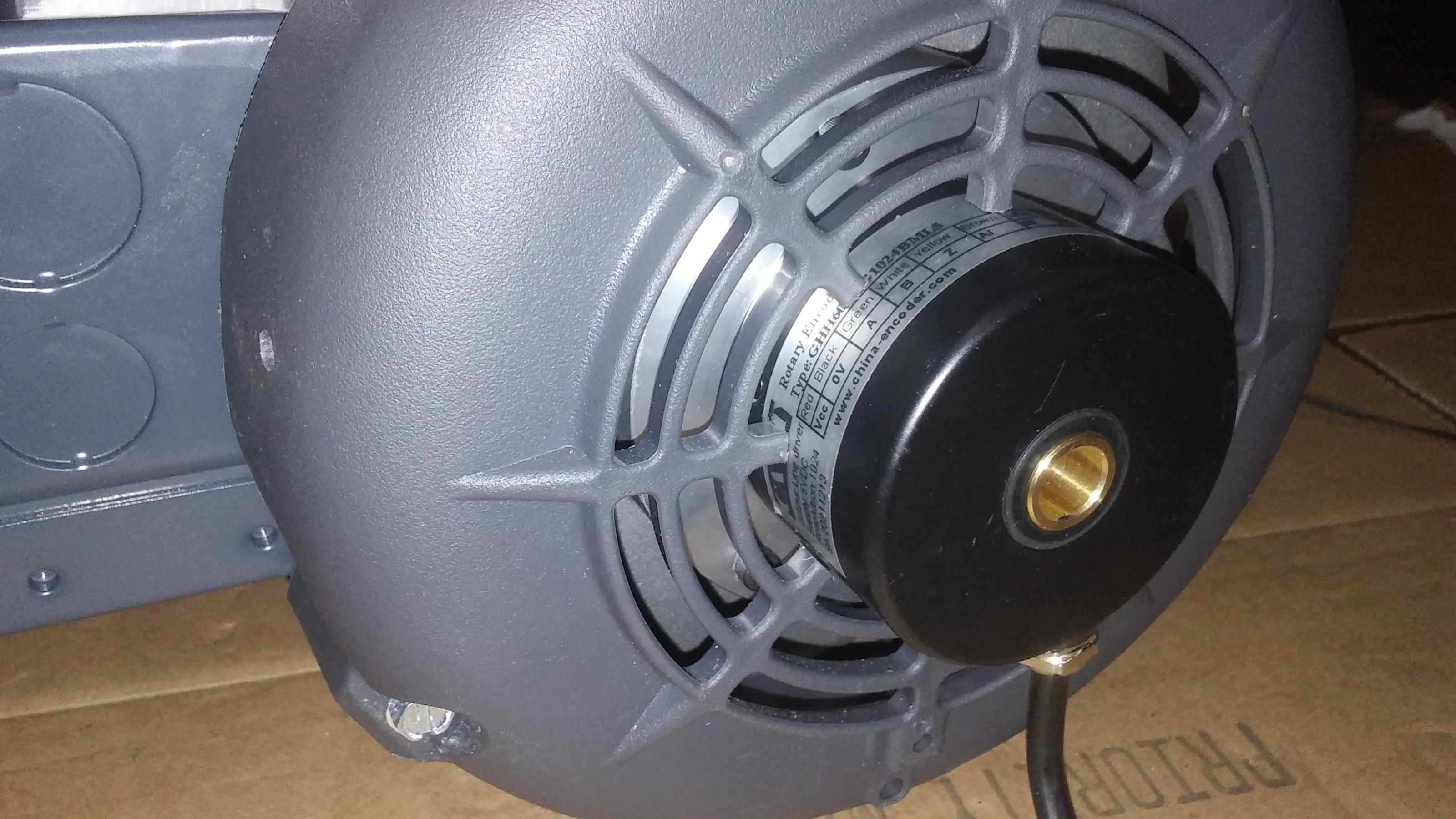
i think i have the encoder sorted out for the most part. it turned out to be a little more involved than what i first thought. the end casting of the motor where the bearings are located on that end turned out to not be flat like i thought it was at first. the end has a slight radius to the casing by design, so i had to spot a face to get something flat to mount the encoder to. just like everything else these days there is not a lot of meat on the casting so i wanted to only take what i needed which was hardly anything to keep it strong and as thick as i can.
thinking about how it all goes together was a bit tricky because of how it all goes together, getting to the set screws on the encoder is the problem area. i will have to drill an access hole in the side of the encoder mount and in the side of the plastic cover to be able to get to the set screws for the encoder. but i need to make a trip to the hardware store to get some M4 cap screws. metric and imperial mixed together is enough to make you nuts")
always some kind of speed bump to get over it seems with this project
thinking about how it all goes together was a bit tricky because of how it all goes together, getting to the set screws on the encoder is the problem area. i will have to drill an access hole in the side of the encoder mount and in the side of the plastic cover to be able to get to the set screws for the encoder. but i need to make a trip to the hardware store to get some M4 cap screws. metric and imperial mixed together is enough to make you nuts
always some kind of speed bump to get over it seems with this project
Please Log in or Create an account to join the conversation.
- machinedude
-
Topic Author
- Offline
- Platinum Member
-
Less
More
- Posts: 715
- Thank you received: 312
06 Feb 2022 01:08 #234072
by machinedude
Replied by machinedude on topic what to do with a free scrap dumpster find ?
just some more pictures of how it all turned out. i will admit i did cheat a little and had to extend an allen wrench since a standard length one was not long enough to get to the set screws. i tried to get more pictures but a few did not get saved as i was taking them so i can't show that part. but here is what i have so far.
the encoder mount has a side thru hole into the bore which lines up with the set screws and the plastic cove also has a hole in line with the encoder mount you can see all of this in the pictures. the encoder mount has an undercut in the middle section the reason for this is i did not face a complete surface on the casting so what i ended was a flat ring on the end casting with a high spot in the center, the under cut in the center of the mount is just clearance for the high spot. these castings are paper thin in my opinion. nothing is made well anymore. because things are so thin these days you have ribs cast into the casting and i made the mount before i even seen what was going on inside. but it was tricky getting some tapped hole in the cast to attach the mount and miss the ribs in the casting. it took me a lot of time just to get things lined up to miss all the ribs.
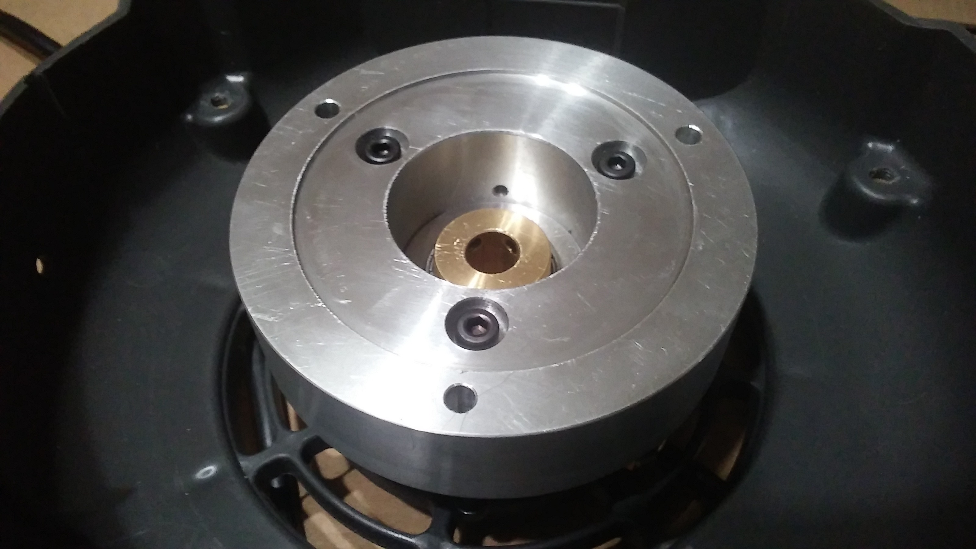
the encoder mount has a side thru hole into the bore which lines up with the set screws and the plastic cove also has a hole in line with the encoder mount you can see all of this in the pictures. the encoder mount has an undercut in the middle section the reason for this is i did not face a complete surface on the casting so what i ended was a flat ring on the end casting with a high spot in the center, the under cut in the center of the mount is just clearance for the high spot. these castings are paper thin in my opinion. nothing is made well anymore. because things are so thin these days you have ribs cast into the casting and i made the mount before i even seen what was going on inside. but it was tricky getting some tapped hole in the cast to attach the mount and miss the ribs in the casting. it took me a lot of time just to get things lined up to miss all the ribs.
Attachments:
The following user(s) said Thank You: tommylight
Please Log in or Create an account to join the conversation.
- machinedude
-
Topic Author
- Offline
- Platinum Member
-
Less
More
- Posts: 715
- Thank you received: 312
06 Feb 2022 17:31 - 07 Feb 2022 23:36 #234129
by machinedude
Replied by machinedude on topic what to do with a free scrap dumpster find ?
So while i was working on all this motor stuff i took a closer look at how the old machine drove the lead screw to drive the head up and down the columns. what i found out was more or less the center line distance between the two gears used to do this. the original ratio was 4:1 but that's pretty slow with a 5mm pitch screw even with a servo rated at 5000 RPM. that would only deliver about 250 IMP i can change the ratio to 2:1 and get 500 IMP which is a lot closer to where i would like to be. i can get gears to do this and not get into to heavy of a modification. i actually was able to look the part numbers up and get the pressure angle and pitch diameter of the gears to figure out the spacing. the only issue with gears is backlash. smaller gears have more backlash than the larger sets.
i did see some anti backlash gears that used two gears and spring load them to remove backlash but it looked like something for larger gear sets. timing belts are far better with backlash but the 15mm wide small ones i have played around with are not up to this task. i would probably need something like the drive on the motor at the very least probably something like a 25mm width would even be better.
if anybody has any suggestions i'm all ears in the mean time i will look into gates GT4 options and see if i can find a solution there? right now the center line spacing is only 1.875 inches but i could probably open it up another inch if i have too.
i did see some anti backlash gears that used two gears and spring load them to remove backlash but it looked like something for larger gear sets. timing belts are far better with backlash but the 15mm wide small ones i have played around with are not up to this task. i would probably need something like the drive on the motor at the very least probably something like a 25mm width would even be better.
if anybody has any suggestions i'm all ears
in the mean time i will look into gates GT4 options and see if i can find a solution there? right now the center line spacing is only 1.875 inches but i could probably open it up another inch if i have too.
Last edit: 07 Feb 2022 23:36 by machinedude. Reason: REMOVED SOME BAD INFO.
Please Log in or Create an account to join the conversation.
- machinedude
-
Topic Author
- Offline
- Platinum Member
-
Less
More
- Posts: 715
- Thank you received: 312
08 Feb 2022 00:03 #234309
by machinedude
Replied by machinedude on topic what to do with a free scrap dumpster find ?
Boston gear has a PFD on their web sit at the end of the PDF they have a lot of technical information on gears that's handy. most likely it would be to large to post here so look them up if you have a need for information on gears.
the amount of backlash is based on the diametral pitch of the ratio change gear(spur gear) the larger of the two. the pinion refers to the smaller gear. the diametral pitch is the number of teeth around the circumference per inch of circumference in my case the D.P. is 16 so that puts me in the .003 range of backlash. i thought it was far worse than this because i confused the pitch diameter and the diametral pitch at first. gears are a specialty section of machining and i have never got into this section. but here is a screen grab of some basic guided lines on backlash and center distance placings and how slight changes to the center distance of shafts can play into the backlash.
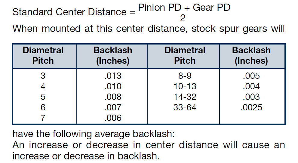
the amount of backlash is based on the diametral pitch of the ratio change gear(spur gear) the larger of the two. the pinion refers to the smaller gear. the diametral pitch is the number of teeth around the circumference per inch of circumference in my case the D.P. is 16 so that puts me in the .003 range of backlash. i thought it was far worse than this because i confused the pitch diameter and the diametral pitch at first. gears are a specialty section of machining and i have never got into this section. but here is a screen grab of some basic guided lines on backlash and center distance placings and how slight changes to the center distance of shafts can play into the backlash.
Attachments:
Please Log in or Create an account to join the conversation.
- machinedude
-
Topic Author
- Offline
- Platinum Member
-
Less
More
- Posts: 715
- Thank you received: 312
08 Feb 2022 00:32 #234311
by machinedude
Replied by machinedude on topic what to do with a free scrap dumpster find ?
after looking some more the gear set up is what i will probably end up sticking too. you can take the backlash out with springs but this is more of a light duty solution and you can do it buy using two gears one on a hub staked to the shaft and a second that spins on the hub and then set with locking screws. the second option is kinda like a double nut on a lead screw loaded in opposing directions. this is something that would need adjusted over time but a more robust drive i think.
a 14.5 degree pressure angle is what was on the machine to begin with and this would be better suited over a 20 degree pressure angle since the 14.5 degree angle runs smoother than a 20 degree and can run faster. just something that pertains to my situation.
down side is i found gear stock so i could custom make what i need but i only found 2 places that sell it an the one place is way to expensive and the other place only offers sock with a 20 degree pressure angle. so this is still up in the air.
Please Log in or Create an account to join the conversation.
- machinedude
-
Topic Author
- Offline
- Platinum Member
-
Less
More
- Posts: 715
- Thank you received: 312
09 Feb 2022 22:16 #234433
by machinedude
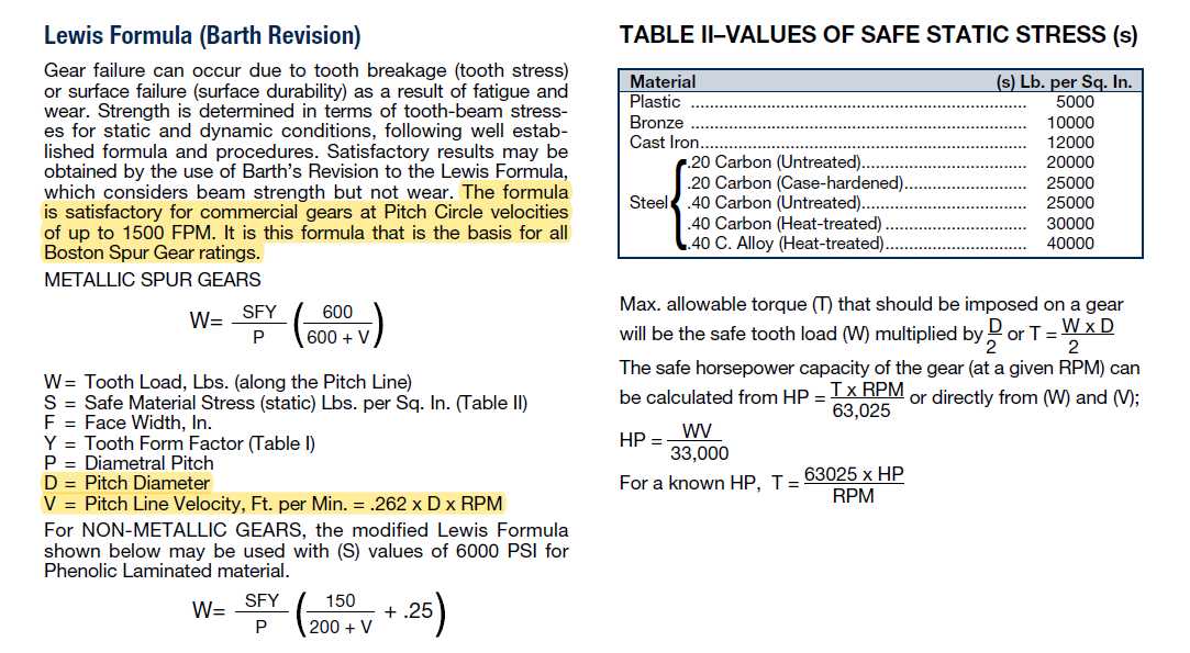 this was the only thing i could find on speed limitations for these spur gears. so based on this i can get about 4,500 RPM on the smaller gear and keep it within the limits. but running that fast i think i will have to keep these gears in an oil bath if they are to last any length of time. i can't get away from this being costly. i think my starting point will be switching to a 2:1 ratio to drive the ball screw since i can run that ratio and not have to change anything as far as center line spacing of the shafts. at that ratio. the ball screw rotation will be in a range of speed that i can put an oil seal on the shaft and make some kind of housing for the gears and still have a decent rapid rate on the heavy lifting axis. the extra torque on a reduction with help keep things moving and the ratio will produce rapids more in tune with what i would like to see. a gear drive is noisy so this will help keep noise down as an added plus as well.
the cheapest solution i can find is just to buy a second gear and modify the two larger gears to create an anti backlash gear. so 3 gears will rum me $110 plus oil seals and material for the housing so not very cheap to drive a screw but options are limited and i think this is my best option.
i would think a lot of the information on the gears here would carry over and apply to rack drives so this might help others.
Replied by machinedude on topic what to do with a free scrap dumpster find ?
the cheapest solution i can find is just to buy a second gear and modify the two larger gears to create an anti backlash gear. so 3 gears will rum me $110 plus oil seals and material for the housing so not very cheap to drive a screw but options are limited and i think this is my best option.
i would think a lot of the information on the gears here would carry over and apply to rack drives so this might help others.
Attachments:
Please Log in or Create an account to join the conversation.
- machinedude
-
Topic Author
- Offline
- Platinum Member
-
Less
More
- Posts: 715
- Thank you received: 312
16 Feb 2022 13:39 - 16 Feb 2022 13:42 #235040
by machinedude
Replied by machinedude on topic what to do with a free scrap dumpster find ?
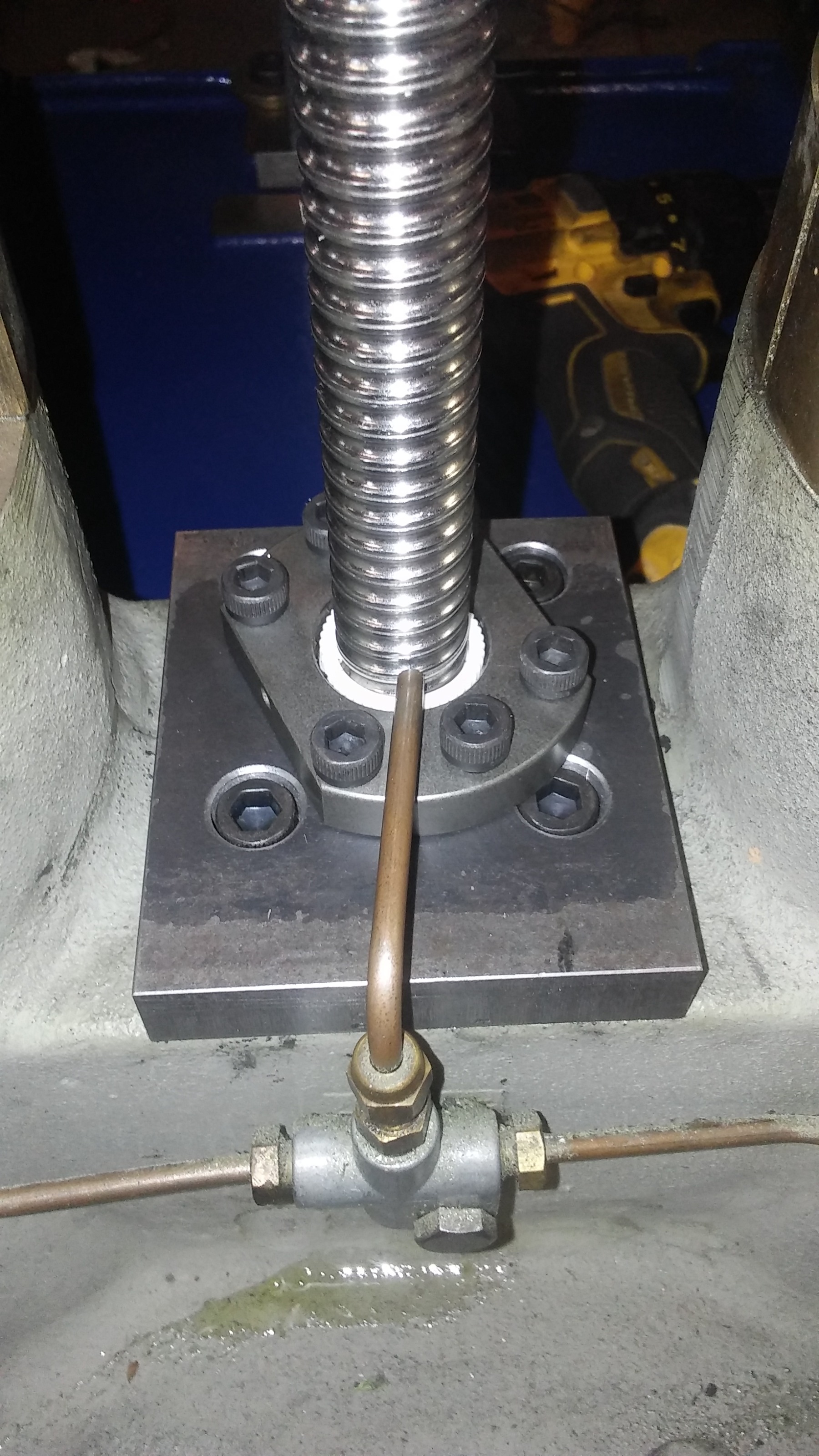
had i little bit of time to start the motor mount parts of this build. i have some screw jacks that will attach and act as the belt tension to slide the motor mounting plate on the stand offs. the motor mounting plate just has some slots and a 1/2 13 bolt on both side to lock it in place. the screw jacks are just to lift the motor mount since it has some weight to it to make belt adjust easy.
i also have some new gears to drive the ball screw. i switched to a 2:1 ratio the original set up was 4:1 but that's pretty slow with a 5mm ball screw. i found a drive sizing program from ABB just to get some basic info and it looks like it should work fine. i also picked up some oil seals incase i can fit the gears in a case but space is limited so i have them if i need them. i also picked up a din rail power supply just for the cooling fans not sure if that was the best solution but it was easy enough.
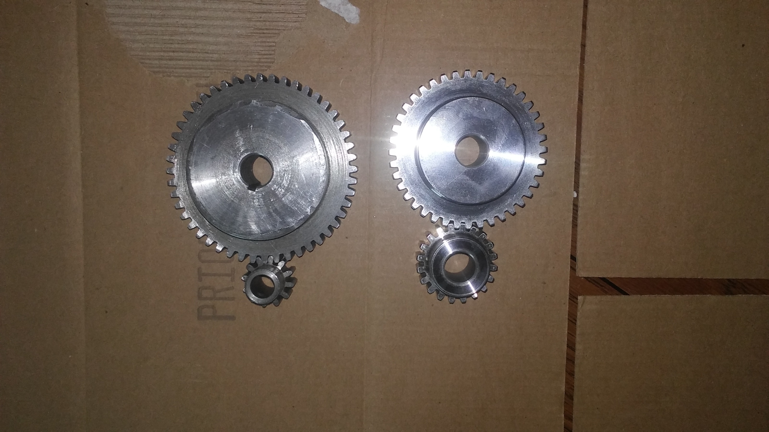
the larger gear will attach to the the ball screw. rather than a key i will just roll pin it to the shaft and use the nut for the ball screw to to lock it down. the set of gears on the left are original and the ones on the right are what i will switch too. simple but should work just as well as being keyed. i have an extra large gear in case i need to do something about backlash as well but will probably see exactly what is going on before i commit to something more complicated.
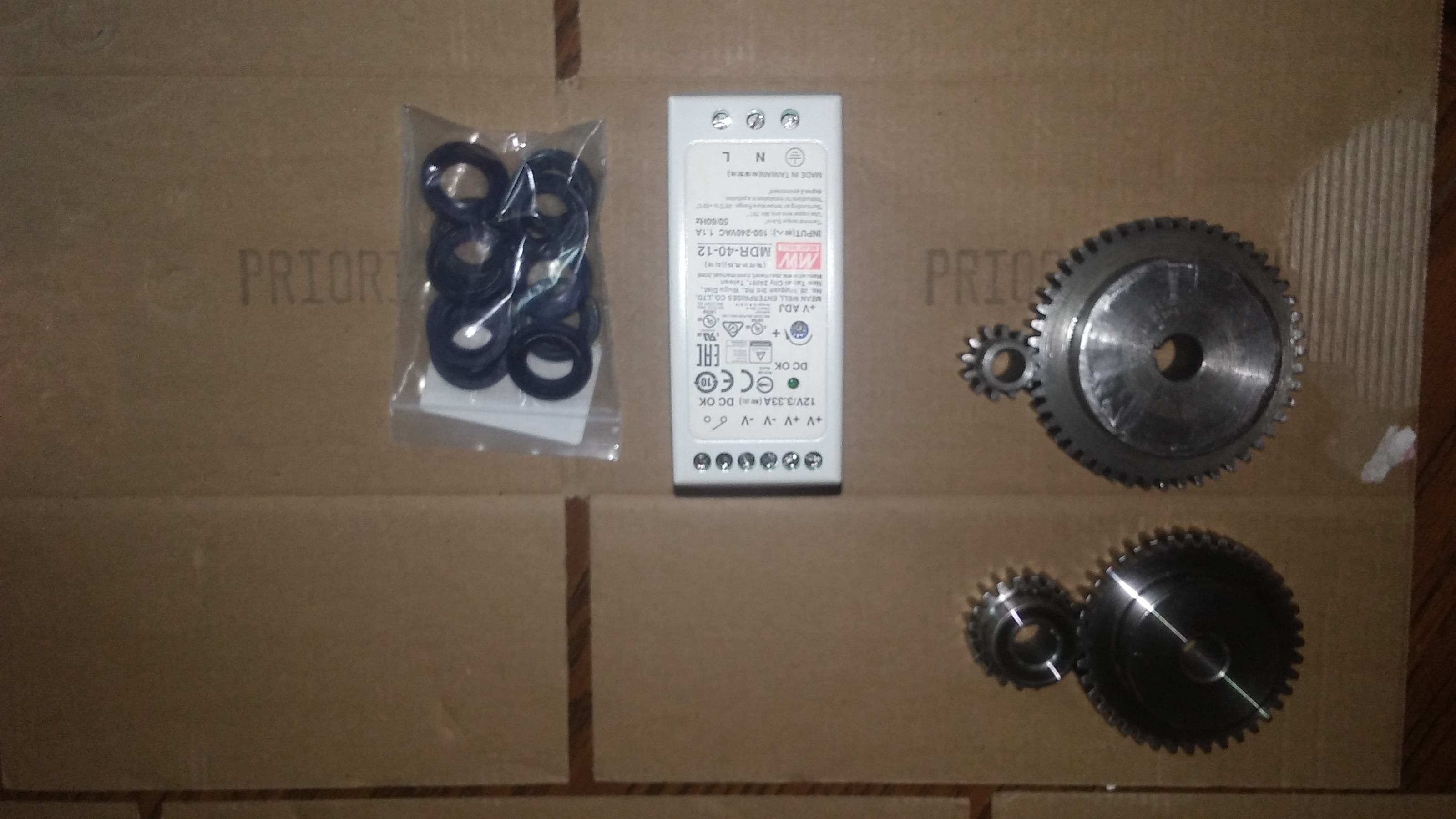
i also have some new gears to drive the ball screw. i switched to a 2:1 ratio the original set up was 4:1 but that's pretty slow with a 5mm ball screw. i found a drive sizing program from ABB just to get some basic info and it looks like it should work fine. i also picked up some oil seals incase i can fit the gears in a case but space is limited so i have them if i need them. i also picked up a din rail power supply just for the cooling fans not sure if that was the best solution but it was easy enough.
the larger gear will attach to the the ball screw. rather than a key i will just roll pin it to the shaft and use the nut for the ball screw to to lock it down. the set of gears on the left are original and the ones on the right are what i will switch too. simple but should work just as well as being keyed. i have an extra large gear in case i need to do something about backlash as well but will probably see exactly what is going on before i commit to something more complicated.
Attachments:
Last edit: 16 Feb 2022 13:42 by machinedude.
The following user(s) said Thank You: tommylight
Please Log in or Create an account to join the conversation.
- machinedude
-
Topic Author
- Offline
- Platinum Member
-
Less
More
- Posts: 715
- Thank you received: 312
22 Feb 2022 13:04 #235522
by machinedude
Replied by machinedude on topic what to do with a free scrap dumpster find ?
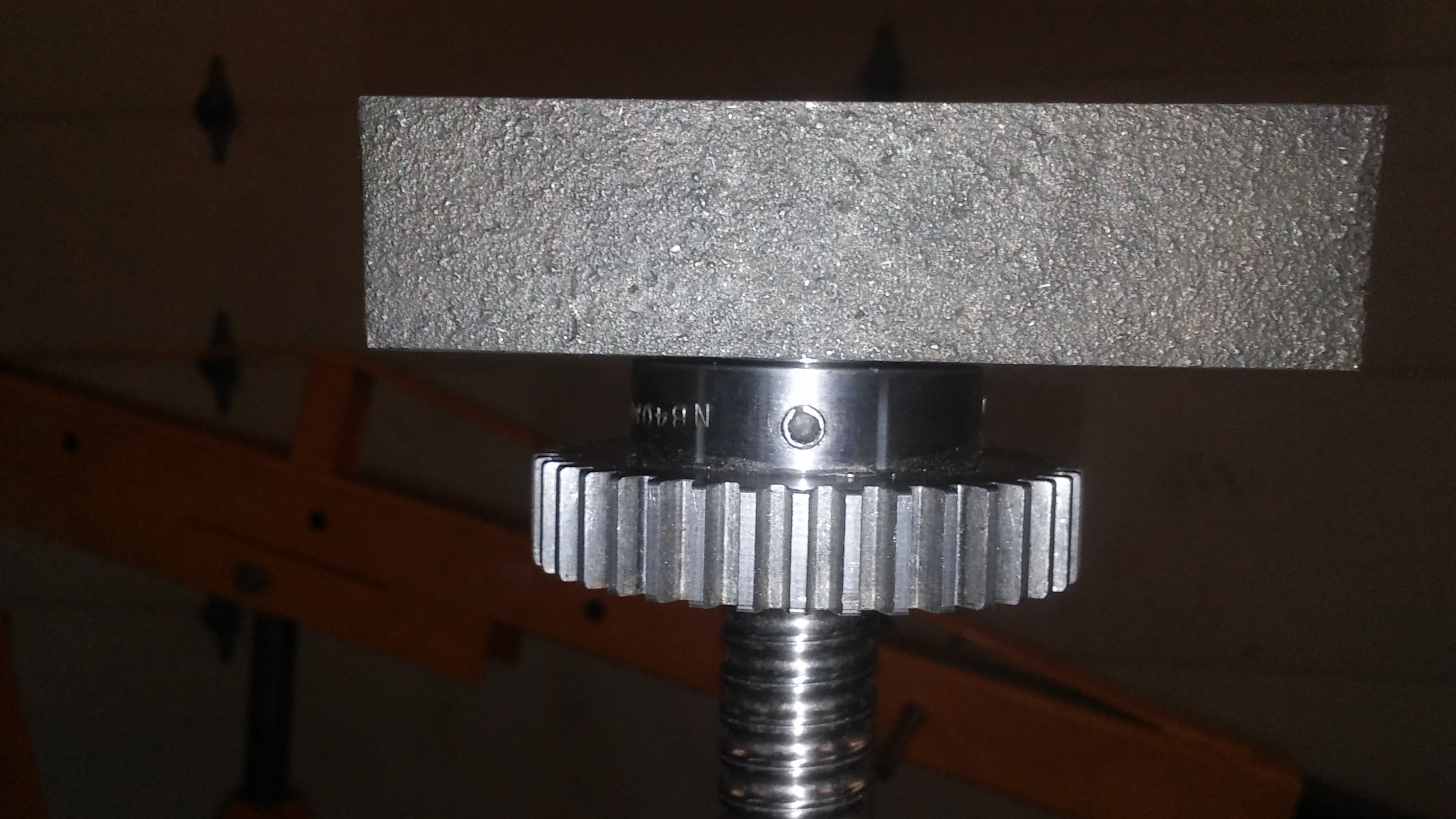
i started to work on the lead screw for the head and was thinking backlash might be an issue with the gears that drive it, but i don't think it will be an issue after all, since the gear only has a typical .003 of backlash with standard centerline spacing i think it can be adjusted to as close as you can get before things bind. the pinion gear is fixed to the head but the ball screw and gear attached can float in any direction. the holes that mount the ball nut and bearing block at the end have some clearance in them so you can actually adjust the shaft to the fixed pinion gear by about .01 in what ever direction you need to go.
i may have been over thinking this
i may have been over thinking this
Please Log in or Create an account to join the conversation.
- machinedude
-
Topic Author
- Offline
- Platinum Member
-
Less
More
- Posts: 715
- Thank you received: 312
28 Feb 2022 22:23 - 28 Feb 2022 22:24 #236043
by machinedude
Replied by machinedude on topic what to do with a free scrap dumpster find ?
had more time than usual to work on this but it was not by choice. i have a love hate relationship with my truck. i love it because it's paid for but i hate it when it comes time to get it inspected for the year to keep it road legal. so in between waiting for prats to come so i could work on that i was working on this project since i was trapped at home
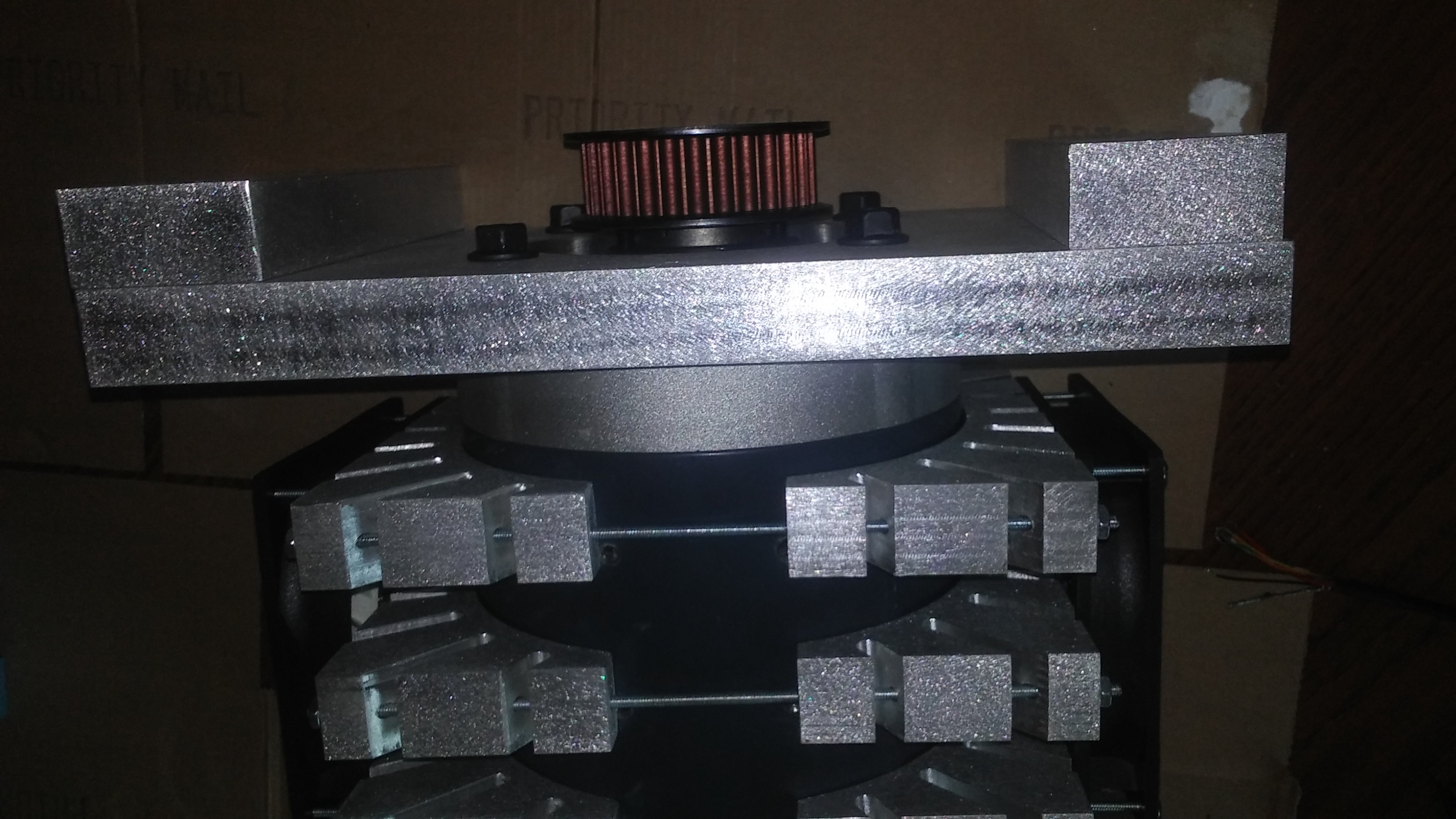
needed to have a place to attach probably 60lbs of motor and upgrades too and drive it all up and down. i need to open the back side of the cast iron block the houses the bearing for the shaft so i can get to the nut better and probably slot the cast iron so i can get to the set screw on the nut as well. i still have a bunch of little stuff to sort out but i'm getting close to getting thing attached and back on the machine at least.
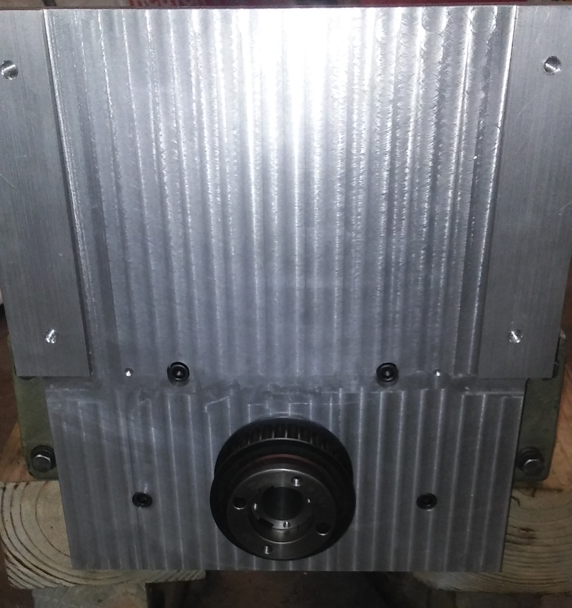
needed to have a place to attach probably 60lbs of motor and upgrades too and drive it all up and down. i need to open the back side of the cast iron block the houses the bearing for the shaft so i can get to the nut better and probably slot the cast iron so i can get to the set screw on the nut as well. i still have a bunch of little stuff to sort out but i'm getting close to getting thing attached and back on the machine at least.
Attachments:
Last edit: 28 Feb 2022 22:24 by machinedude.
The following user(s) said Thank You: tommylight
Please Log in or Create an account to join the conversation.
Time to create page: 0.679 seconds