AX58100
- COFHAL
- Offline
- Platinum Member
-

Less
More
- Posts: 457
- Thank you received: 62
23 Feb 2025 15:10 - 23 Feb 2025 15:14 #322367
by COFHAL
Replied by COFHAL on topic MAX VELOCITY STEP.
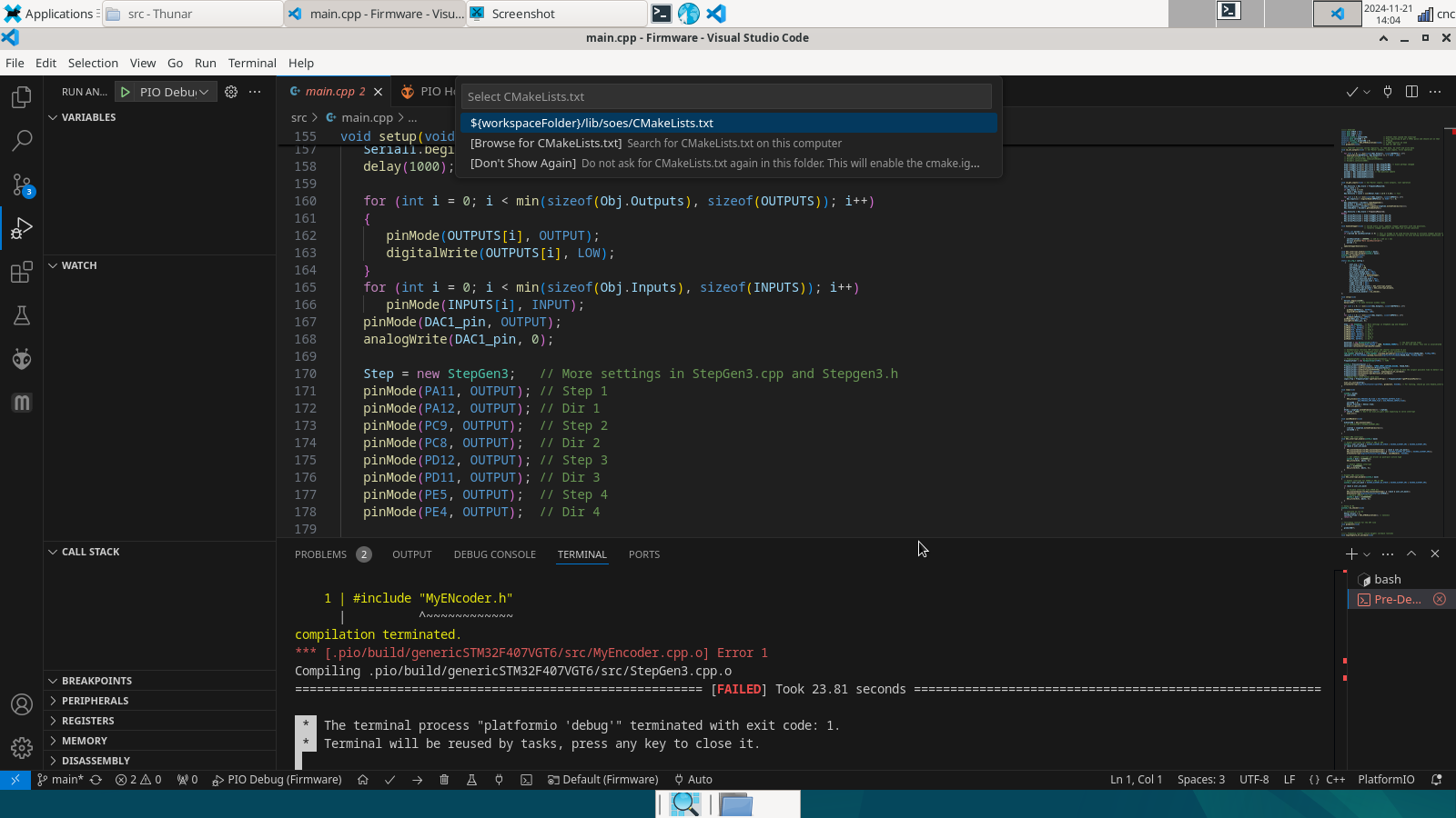
I did indeed modify JOINT_N_SCALE to match the drive configuration and the value in the INI file. and it works fine now. The axis moves exactly with the commanded value. Changing the BASE_PERIOD value to 10000 in the firmware also increases the speed without the joint tracking error occurring.
The only drawback is that if one modifies the STEP_SCALE parameter in the drive, the firmware would necessarily have to be recompiled. That is why it seems like a good idea to remove these parameters from the firmware so that they can be modified at any time.
The only drawback is that if one modifies the STEP_SCALE parameter in the drive, the firmware would necessarily have to be recompiled. That is why it seems like a good idea to remove these parameters from the firmware so that they can be modified at any time.
Attachments:
Last edit: 23 Feb 2025 15:14 by COFHAL.
Please Log in or Create an account to join the conversation.
- Hakan
- Offline
- Platinum Member
-
Less
More
- Posts: 1317
- Thank you received: 453
23 Feb 2025 20:04 - 23 Feb 2025 20:06 #322394
by Hakan
Replied by Hakan on topic MAX VELOCITY STEP.
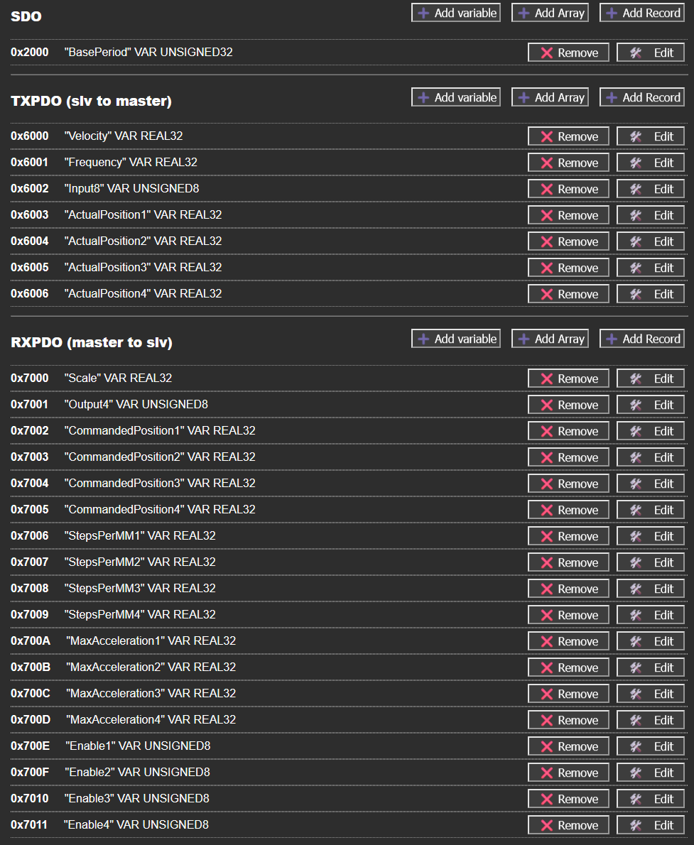
I have now this list of PDOs and one SDO.
Default values are in the PDO/SDO.
I have also changed Digital Input and Digital Output data types. I will provide an example ethercat-conf.xml
Default values are in the PDO/SDO.
I have also changed Digital Input and Digital Output data types. I will provide an example ethercat-conf.xml
Attachments:
Last edit: 23 Feb 2025 20:06 by Hakan.
The following user(s) said Thank You: COFHAL
Please Log in or Create an account to join the conversation.
- SOLD
- Offline
- Premium Member
-

Less
More
- Posts: 122
- Thank you received: 13
01 Mar 2025 07:25 #322911
by SOLD
Replied by SOLD on topic AX58100
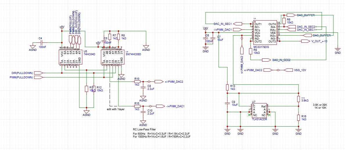
Hi, Thanks for your further development. I have been away from Ethercat for a long time. In the past I have been experimenting with designing a +-10V PWM for my analog spindle. It works but I have not tested it in practice. I will add this circuit to the Ethercat board.
Attachments:
Please Log in or Create an account to join the conversation.
- Hakan
- Offline
- Platinum Member
-
Less
More
- Posts: 1317
- Thank you received: 453
01 Mar 2025 12:41 #322919
by Hakan
Replied by Hakan on topic AX58100
Haven't been working on this particular board a lot since I don't use it myself. Been busy with a voltage reader for plasma and IO, for my plasma cutter and that works great.
If you continue to use the STM32F407 you should check that there are free timers available. Probable there are, but I used a lot of timers I remember.
Earlier in the thread there is an attachment with spindle control schematics, maybe you already had a look on that one.
My spindles are all controlled via Modbus/VFD and the 3V analog output was put there for good measure.
There could have been connectors for I2C and SPI to easily add on functionality controlled by the STM32. Maybe something you can think of.
The following user(s) said Thank You: SOLD
Please Log in or Create an account to join the conversation.
- COFHAL
- Offline
- Platinum Member
-
Less
More
- Posts: 457
- Thank you received: 62
30 Apr 2025 17:51 #327373
by COFHAL
Replied by COFHAL on topic MAX VELOCITY STEP.
I see that I've updated the information related to the AX5800 card. Now I have some questions:
I see that I created some enable pins. I assume they are to enable the output of each of the step generators. In the XML file for LINUXCNC, these pins appear as BIT, but I don't know how to configure them correctly in the EEPROM generator file. Bit variables don't appear there. In that same file it appears
<pdoEntry idx="6001" subIdx="01" bitLen="32" halPin="Frequency" halType="float-ieee"/>
</pdo>
<pdo idx="1a01">
<pdoEntry idx="6001" subIdx="01" bitLen="8" halPin="DI1" halType="u32"/>
<pdoEntry idx="6001" subIdx="02" bitLen="8" halPin="DI2" halType="u32"/>
<pdoEntry idx="6001" subIdx="03" bitLen="8" halPin="DI3" halType="u32"/>
<pdoEntry idx="6001" subIdx="04" bitLen="8" halPin="DI4" halType="u32"/>
It's not clear to me what function those DI pins have and how they are programmed in the EEPROM generator.
Please Log in or Create an account to join the conversation.
- Hakan
- Offline
- Platinum Member
-
Less
More
- Posts: 1317
- Thank you received: 453
01 May 2025 05:46 #327405
by Hakan
Replied by Hakan on topic MAX VELOCITY STEP.
I think there is something not quite right in the eeprom_generator with bits, so I use uint8 instead.
And then create a bit pin in linuxcnc with
<pdoEntry idx="600x" subIdx="01" bitLen="8" halPin="enable1" halType="bit"/>
Those DI pins are the input pins, for switches etc. I think the halType should be "bit" for them.
What do you do in the code with the enable information?
And then create a bit pin in linuxcnc with
<pdoEntry idx="600x" subIdx="01" bitLen="8" halPin="enable1" halType="bit"/>
Those DI pins are the input pins, for switches etc. I think the halType should be "bit" for them.
What do you do in the code with the enable information?
Please Log in or Create an account to join the conversation.
- COFHAL
- Offline
- Platinum Member
-
Less
More
- Posts: 457
- Thank you received: 62
13 Aug 2025 15:10 #333339
by COFHAL
Replied by COFHAL on topic AX58100 last firmware
I see that the EaserCAT-3000 board firmware has been updated on Github. As you mentioned earlier, you left out the step scale so it could be modified from the INI file. You also added enable pins, but I don't know how to use them. Could you explain these changes a little more?
Please Log in or Create an account to join the conversation.
- Hakan
- Offline
- Platinum Member
-
Less
More
- Posts: 1317
- Thank you received: 453
13 Aug 2025 16:06 #333346
by Hakan
Replied by Hakan on topic AX58100 last firmware
I answered on the github issue tracker, but you set number of steps with normal "setp" in the hal file.
The new Enable PDO/Pin should be connected to net x-enable, that way it only generates steps when the machine is "on".
Like soYou also have MaxAcceleration as a new PDO and the guideline is some 25% higher than ACCELERATION in the ini file.
The new Enable PDO/Pin should be connected to net x-enable, that way it only generates steps when the machine is "on".
Like so
setp lcec.0.E3000.StepsPerMM1 200
net x.enable lcec.0.E3000.Enable1
The following user(s) said Thank You: COFHAL
Please Log in or Create an account to join the conversation.
- COFHAL
- Offline
- Platinum Member
-
Less
More
- Posts: 457
- Thank you received: 62
15 Aug 2025 19:00 #333478
by COFHAL
Replied by COFHAL on topic AX58100 last firmware
The CAT3000 definitely doesn't work with Linuxcnc with the latest version. If I connect it to TwinCAT, there's no problem. I can go to OP state, the inputs and outputs work, the encoder too, but with LNC, nothing works; it doesn't go to OP state. Something very strange is that many Enable pins are generated, 8 in total for each Enable, as seen in the photo. I don't know if the problem could be the ethercat-conf file.
Please Log in or Create an account to join the conversation.
- COFHAL
- Offline
- Platinum Member
-
Less
More
- Posts: 457
- Thank you received: 62
15 Aug 2025 19:06 #333479
by COFHAL
Replied by COFHAL on topic AX58100 last firmware
Another thing I noticed is that when looking at the circuit diagram the +24 volt input is not connected to anything, the same on the PCB this pin is not connected either, only -24 volts is connected to the current limiting resistors at the inputs of the optocouplers of the inputs.
Please Log in or Create an account to join the conversation.
Time to create page: 0.178 seconds