- Other Stuff
- Show Your Stuff
- Vertical Machining Centre Retrofit with Chinese Servo Drives Build Thread (NZ)
Vertical Machining Centre Retrofit with Chinese Servo Drives Build Thread (NZ)
- Becksvill
- Offline
- Elite Member
-

Less
More
- Posts: 206
- Thank you received: 103
11 May 2020 03:04 #167323
by Becksvill
Replied by Becksvill on topic Vertical Machining Centre Retrofit with Chinese Servo Drives Build Thread (NZ)
I am getting a bit stuck I think working out what I actually want to tune. my servo drives have both a velocity Pid loop and a position pid loop. I am getting a bit stuck working out which bit to tune first. etc
currently I am just changing values in the servo drive and seeing what they change and trying to graph them.
actually just to confirm this is how I think my setup is working
the commanded position is given to the stepgens and they run a pid loop with the stepgen feedback. (this is a stock pncconf setup i think) I shouldn't have altered the tuning within linuxcnc
and then the actual encoder position goes the to DRO( joint feedback etc)
so I can see the actual position of the motor in the DRO but that doesn't change the PID loop.
if anyone has any ideas I would appreciate it
Please Log in or Create an account to join the conversation.
- tommylight
-

- Offline
- Moderator
-

Less
More
- Posts: 21691
- Thank you received: 7414
11 May 2020 07:52 #167338
by tommylight
Replied by tommylight on topic Vertical Machining Centre Retrofit with Chinese Servo Drives Build Thread (NZ)
Some pointers:
Set the stepgen in position mode or default, leave all settings for that axis at default, forget the encoder and check if the machine works properly (or that axis since you have 1 encoder for now). Tune the drive if needed or there are errors in positioning.
Only after you are sure that position mode is working correctly you can continue to close the loop in lLinuxcnc by setting the stepgen mode to velocity for that axis and activating the encoder in the hal fie for the feedback. It should not need much tuning.
The following user(s) said Thank You: Becksvill
Please Log in or Create an account to join the conversation.
- Becksvill
- Offline
- Elite Member
-
Less
More
- Posts: 206
- Thank you received: 103
11 May 2020 09:12 #167353
by Becksvill
Replied by Becksvill on topic Vertical Machining Centre Retrofit with Chinese Servo Drives Build Thread (NZ)
Hi Tommy
I will check that I have the stepgen in position mode. I think it is.
currently I have the encoder unconnected to the PID Loop but still updating the DRO so I can check the actual encoder position.
I have halscope all working ok I think and I can graph the various signals fine.
what I am actually struggling with is not a linuxcnc thing at all.
In the servo manual the tuning parameters are called different names to what linuxcnc calls things. EG I don't know for sure what is P what is I and what is D
by the look of things there is a velocity loop in the drive that needs to be tuned as well as the position loop inside the drive. As you advised I am only using the halscope to graph the error. the halscope PID is set up as default values
I will take some photos tomorrow showing how I have halscope setup
regards
Andrew
Please Log in or Create an account to join the conversation.
- tommylight
-
- Offline
- Moderator
-
Less
More
- Posts: 21691
- Thank you received: 7414
11 May 2020 09:19 #167354
by tommylight
Replied by tommylight on topic Vertical Machining Centre Retrofit with Chinese Servo Drives Build Thread (NZ)
P = proportional
I = integral
D = derivative
Also search for granite devices, argon drive tuning, has plenty of info about tuning those types of drives that might help you.
I = integral
D = derivative
Also search for granite devices, argon drive tuning, has plenty of info about tuning those types of drives that might help you.
The following user(s) said Thank You: Becksvill
Please Log in or Create an account to join the conversation.
- Todd Zuercher
-

- Offline
- Platinum Member
-

Less
More
- Posts: 4753
- Thank you received: 1458
11 May 2020 12:53 #167368
by Todd Zuercher
Replied by Todd Zuercher on topic Vertical Machining Centre Retrofit with Chinese Servo Drives Build Thread (NZ)
There are a couple of different type of servo control loops used in drives but most at least vaguely resemble a standard PID loop in their tune-able constants. Some drive manuals will refer to them as Kp Ki and Kd, and some will also have feed forward terms as well. To try to use the drives factory tuning software you probably have to have Windows on a pc and some kind of serial cable to connect it to the drive. (probably RS232). The PC you run the tuning software on does not need to be the one running Linuxcnc, Infact it is probably better if it is not, so that you can run the tuning software and Linuxcnc at the same time.
Without the tuning software and or intimate knowledge of the drives tuning parameters. You are really poking blindly at this thing.
Without the tuning software and or intimate knowledge of the drives tuning parameters. You are really poking blindly at this thing.
The following user(s) said Thank You: tommylight, Becksvill
Please Log in or Create an account to join the conversation.
- Becksvill
- Offline
- Elite Member
-
Less
More
- Posts: 206
- Thank you received: 103
12 May 2020 04:34 #167459
by Becksvill
Replied by Becksvill on topic Vertical Machining Centre Retrofit with Chinese Servo Drives Build Thread (NZ)
hey todd.
I have been trying for months to get the tuning software going on windows7.
I have the software and the usb to serial cable to connect to it. But it can't connect and I have tried all sorts of things to get it to work.
I havn't gotten to the point of learning to snoop the rs485 connection yet.
I am currently trying to do a work around with halscope to tune the drives without the software.
I am currently all connected and reading encoder inputs and sending step and direction signals to the servo drive.
Inside the servo drive there is a position loop controlling a velocity loop that controls a torque loop. (the torque Pid is set by the motor code)
So do you think it is possible to graph the encoder position in halscope and the joint commanded position and also commanded velocity and encoder velocity and be able to use that to know what values to change in the servo drive?
Or am I still running blind?
I know this is not the usual use for halscope. so not sure if it would work
regards
Andrew
Please Log in or Create an account to join the conversation.
- Todd Zuercher
-
- Offline
- Platinum Member
-
Less
More
- Posts: 4753
- Thank you received: 1458
12 May 2020 12:51 #167511
by Todd Zuercher
Replied by Todd Zuercher on topic Vertical Machining Centre Retrofit with Chinese Servo Drives Build Thread (NZ)
Well, I've done more or less that myself before but with different drives. But the drives I was tuning had decent English manuals for tuning and I was able to run the drives tuning software. I used Linuxcnc to simply scope the encoders position and velocity, so I would not have to try to use the only ancient crappy scope we had at the time. My drives required the tuning software to even be able to set the gains, there was no way to access them otherwise. Then I followed the drive's manual for the tuning procedure, either using the tuning software to generate the excitation signals to tune by or using Linuxcnc to generate a simular signal (I tried both), The advantages of the first was that I knew the right signal pulses were used, and for the 2nd I was able to use Linuxcnc to calculate following errors to look at in Halscope. But unlike your situation, I had a manual with detailed step by step tuning instructions written in English by someone for whom English was their first language, not a Google Translate version of a minimal Chinese manual.
Your best option may be to post a link to a copy of the manual for your drives, and ask for help deciphering what parameters you should try to tune and how. Also have you attempted to contact the drive's manufacturer or supplier and ask for support. Sometimes you will get surprisingly adequate help. They may at least be able to tell you why you can't get the tuning software to run and how to fix it.
Your best option may be to post a link to a copy of the manual for your drives, and ask for help deciphering what parameters you should try to tune and how. Also have you attempted to contact the drive's manufacturer or supplier and ask for support. Sometimes you will get surprisingly adequate help. They may at least be able to tell you why you can't get the tuning software to run and how to fix it.
The following user(s) said Thank You: Becksvill
Please Log in or Create an account to join the conversation.
- Becksvill
- Offline
- Elite Member
-
Less
More
- Posts: 206
- Thank you received: 103
12 May 2020 21:42 - 12 May 2020 21:46 #167566
by Becksvill
Replied by Becksvill on topic Vertical Machining Centre Retrofit with Chinese Servo Drives Build Thread (NZ)
Hey Todd
the manual is written in pretty good english and the yuhai servo drives are basicly perfect copies of sigma2 or newer yaskawa servo drives I think. they have all the same gains and similar. The Bill at Yuhai has been really helpful and has given me lots of help. But is staying silent now. I don't know if it is the covid stuff in china and he is busy or he is just ignoring me.. But I kind of have to work it out myself now I think. have no trouble setting up the different parameters now though and doing whatever I want. there is a small lcd screen on the servo and 4 buttons that I can use to change anything I like. the tuning parameters can be adjusted easily that way.
So adjusting tuning parameters is not a problem. actually knowing what to adjust them to and making sure I am trying to graph the right signals is the problem
here is the relevant info in the servo drive manual about tuning. there is also 2 notch filters I can use that are not shown here. I was watching a yaskawa sigma 7 servo tuning tutorial and the info is sort of similar just I only have access to the actual parameters(no tuning software)
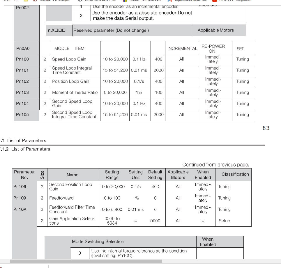
here is a link to the whole manual if you are interested but it is a pretty big manual
drive.google.com/open?id=1B_hC1_C8CejWU2ZDqxzp11reUN28kEXF
I am getting pretty good at connecting Hal signals to scope whatever I want to now.
I have worked out that my servos have 3 tuning loops in them.
there is the Torque PID loop. that is set at factory by a motor code that you set in the software.
next is the velocity loop. I have to set this
finally there is a position loop. which I can set
as you will see from the image above there are 8 tuning parameters I think.
currently I am commanding a move in linuxcnc and the 7i76 sends a whole bunch of step pulses to the drive. I think that means that the position and the velocity loop need to be tuned at the same time which may be a problem maybe I need to jog the servo internally instead and try tune the servo loop that way. but then I loose Halscope as I can't map the velocity error. also I am not sure what set s the acceleration in the drive. there are no acceleration parameters that I can find just the speed loop gains. I am wondering if they are how I set the acceleration in the servo. as I have read here that it needs to be slightly higher than the acceleration in linuxcnc the servo drive can keep up.
anyway if you have any hints I would appreciate it.
regards
Andrew
the manual is written in pretty good english and the yuhai servo drives are basicly perfect copies of sigma2 or newer yaskawa servo drives I think. they have all the same gains and similar. The Bill at Yuhai has been really helpful and has given me lots of help. But is staying silent now. I don't know if it is the covid stuff in china and he is busy or he is just ignoring me.. But I kind of have to work it out myself now I think. have no trouble setting up the different parameters now though and doing whatever I want. there is a small lcd screen on the servo and 4 buttons that I can use to change anything I like. the tuning parameters can be adjusted easily that way.
So adjusting tuning parameters is not a problem. actually knowing what to adjust them to and making sure I am trying to graph the right signals is the problem
here is the relevant info in the servo drive manual about tuning. there is also 2 notch filters I can use that are not shown here. I was watching a yaskawa sigma 7 servo tuning tutorial and the info is sort of similar just I only have access to the actual parameters(no tuning software)
here is a link to the whole manual if you are interested but it is a pretty big manual
drive.google.com/open?id=1B_hC1_C8CejWU2ZDqxzp11reUN28kEXF
I am getting pretty good at connecting Hal signals to scope whatever I want to now.
I have worked out that my servos have 3 tuning loops in them.
there is the Torque PID loop. that is set at factory by a motor code that you set in the software.
next is the velocity loop. I have to set this
finally there is a position loop. which I can set
as you will see from the image above there are 8 tuning parameters I think.
currently I am commanding a move in linuxcnc and the 7i76 sends a whole bunch of step pulses to the drive. I think that means that the position and the velocity loop need to be tuned at the same time which may be a problem maybe I need to jog the servo internally instead and try tune the servo loop that way. but then I loose Halscope as I can't map the velocity error. also I am not sure what set s the acceleration in the drive. there are no acceleration parameters that I can find just the speed loop gains. I am wondering if they are how I set the acceleration in the servo. as I have read here that it needs to be slightly higher than the acceleration in linuxcnc the servo drive can keep up.
anyway if you have any hints I would appreciate it.
regards
Andrew
Last edit: 12 May 2020 21:46 by Becksvill. Reason: adding servo drive manual
Please Log in or Create an account to join the conversation.
- Becksvill
- Offline
- Elite Member
-
Less
More
- Posts: 206
- Thank you received: 103
14 May 2020 03:14 - 14 May 2020 03:33 #167700
by Becksvill
Replied by Becksvill on topic Vertical Machining Centre Retrofit with Chinese Servo Drives Build Thread (NZ)
Hi guys
(ps for those that don't want to read the whole message here is a question for you... what does a torque ripple look like?)
Got a update for everyone here.. I have been having some sort of success with my tuning efforts after 3 days and about 30 hrs mucking around with values haha. I am getting a feel for what works.
feed forward was a very important parameter to increase. It is at its max value of 100 percent now.
I have gotten the following error down to .03 mm at 8000mm/min rapid speed.
and at 1000mm/min feedrate the max following error is 0.0018 mm though there is a spike up to 0.005 mm at the very start.
But as the video shows I am getting a annoying noise at low speed. I am not sure what it is, but changing the tuning values doesn't seem to change it too much. I assume it is high frequency harmonics. I have tried changing the velocity gain and also tried changing the position gain but haven't had any success. also I tried changing the velocity speed intergral time constant ( I think this is the same as Intregral) changing it to all sorts of values. I haven't brought them all down together...
apart from the sound the tuning in pretty good and I am happy with it. once I close the loop properly to linuxcnc with the 7i89 encoder board I might use a little bit of (intergral) to cut down any last little errors.
On these servos I have very high ppr absolute encoders that can output a incremental encoder pulse at whatever PPR I choose. So I started at 2500 ppr then changed to 10000 ppr
and finally I have changed to 25000 ppr which the mesa card seems to handle fine. remembering that is is quadrature signals and gets multiplied by 4 in linuxcnc. so that is 1,00,000 ppr (running through a 16 mm pitch ballscrew. so divide the total ppr by 16 to get a scale of 6250 which counts fine.
I saw someones reply on the emc user list and he was running a 7000 ppr encoder at 3000 rpm so I thought so long as I stay under that I will be fine..
But the higher encoder count seemed to stop encoder dithering I think. just that last little bit of accuracy not that it is really needed but it was just a parameter lol and the resolution was there free for the taking.
Currently at 8000mm/min max rapid my machine servo motor max speed is only 500 rpm and the servo max rated rpm is 1500 rpm so I can go quite a bit higher with the rapids if I want. It seems fast enough for now though
accelerations are set at 1500 mm/s2 I think in the ini file
But this high pitch harmonics would be really nice to get rid of! I know I can turn everything down but that will stop my nice and close position loop. and am definitely a fair way away from any bad oscillations. I turned the gains up for fun and that experience was a fair bit different than this sound.
Is it possible that I have a torque ripple?
or can you suggest any ideas to reduce the noise and harmonics. I have some notch filters that I can use on the servo drive but initial testing just seems worst.
regards
Andrew
Last edit: 14 May 2020 03:33 by Becksvill. Reason: fixing links
Please Log in or Create an account to join the conversation.
- Todd Zuercher
-
- Offline
- Platinum Member
-
Less
More
- Posts: 4753
- Thank you received: 1458
14 May 2020 12:38 - 14 May 2020 12:43 #167729
by Todd Zuercher
Replied by Todd Zuercher on topic Vertical Machining Centre Retrofit with Chinese Servo Drives Build Thread (NZ)
Just a little confused, at one point it seems like you are talking about a servo driven spindle, then you seem to be talking about tuning an axis. Which are you talking about, a spindle or an axis? Are you using step/dir as the control signals? If so how fine do you have the step resolution set in your servo? I would suggest setting it at least as fine as the encoder resolution output to Linuxcnc including quadrature.
(PS: I did not see any servo tuning instructions in the manual you posted the link to. They may be in the manual for the tuning software,)
(PS: I did not see any servo tuning instructions in the manual you posted the link to. They may be in the manual for the tuning software,)
Last edit: 14 May 2020 12:43 by Todd Zuercher.
Please Log in or Create an account to join the conversation.
- Other Stuff
- Show Your Stuff
- Vertical Machining Centre Retrofit with Chinese Servo Drives Build Thread (NZ)
Time to create page: 0.252 seconds