- Other Stuff
- Show Your Stuff
- Developments on my Home built 5C CNC Lathe - new spindle and progress on the ATC
Developments on my Home built 5C CNC Lathe - new spindle and progress on the ATC
- NoJo
- Offline
- Elite Member
-

- Posts: 180
- Thank you received: 43
Reverse everything above, and C-axis DRO disappears from display. There is no 'unwind.'
For your LCNC switchkins, I think you can do away with the unwind function and just force the C-axis to home every time you enter/re-enter C-axis mode.
My statement :
then at the end G13.1 home the spindle again. Of course having moved tools to a safe place prior to G13.1. -
was maybe too easy.. Of course the tool must be moved to a safe place, but what is the convention here to do that? Since this would be a move commanded inside the Polar mode, not a Gcoded move, that move would have to be universally applicable. Z zero might be at the workpiece or stock end, or might not if offsets are set, etc, so we can't rely on a move of Z past the Z zero. Since it is probably appropriate to move Z away first, would it be better to do say G50 Z0.0, then G13.1 ?? Or maybe G50 Z0.0 then G50 X0.0, then G13.1 ...
Been trying to generate some Gcode files with a few CAM packages to see how they handle this, but its not clear..
Please Log in or Create an account to join the conversation.
- spumco
- Offline
- Platinum Member
-

- Posts: 2126
- Thank you received: 882
- At 13.1, do nothing - don't re-home as there's no point.
- If you are using another live axial tool, then the next G12.1 will home to the same C-axis orientation
- If you are using a radial live tool you don't need to home it as the C-axis will be back in non-interpolated mode
- EDIT - this will require verification that C-axis stays homed after canceling polar mode
- If you are doing turning/spindle mode, you don't care about the C-axis home
- Use machine coordinates for tool changes
So a polar interpolation sequence looks like this:
- Txx
- G0XnZn [preliminary move]
- Mxx [C-axis mode]
- C-homes as part of M-code (option #1), or
- G0C0 (option #2, separate home command)
- G12.1 [polar mode]
- ... machining moves, including an X lead-out from part
- G13.1 [cancel polar mode, nothing else happens]
- G53 G0 Xn Zn [move to tool change position in machine coordinates]
- ...
- G13.1
- G53 Znn
- G53 Xnn
- Txx
-Ralph
Please Log in or Create an account to join the conversation.
- NoJo
- Offline
- Elite Member
-
- Posts: 180
- Thank you received: 43
Thanks again, been very helpful.
Joe
Please Log in or Create an account to join the conversation.
- NoJo
- Offline
- Elite Member
-
- Posts: 180
- Thank you received: 43
I thought I had Tool Offsets under the belt..Not so it seems.
Lets use just one tool - I establish its offsets in X and Z OK - appears in the tool table as expected.
The lathe is back-tool mode, with it set so in ini as well.
Open Lcnc , Home all axes and load this Gcode file ( with appropriate setup G and M codes, etc)
G7
G18
G01 X40 Z40 F800
G01 X20 Z20 F800
G01 X40 Z0 F800
M30
Display looks like this:
(262)

Then Single step the Gcode - after the T1 M6 G43, display looks like this with the workspace aligned inside the red work area.:
(267)
Continue single step and all is well, - file completes OK.
Now start again, close Lcnc, re-open,
Home all, Load same Gcode file.
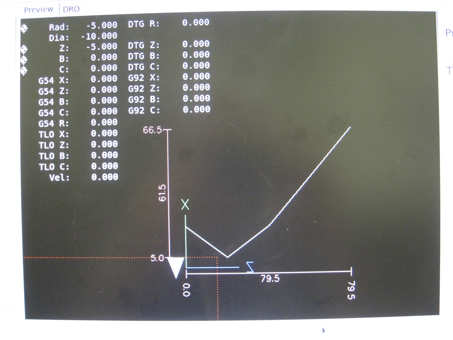
Display looks so:
(269)
Now I wish to set a new workpiece Z zero for tool 1.
In MDI I then do T1 M6 G43.
Then I jog Z to its new Zero position, and do Tool-Touch-Off Z=0.0 ( with mode=tool touch off to workpiece selected)
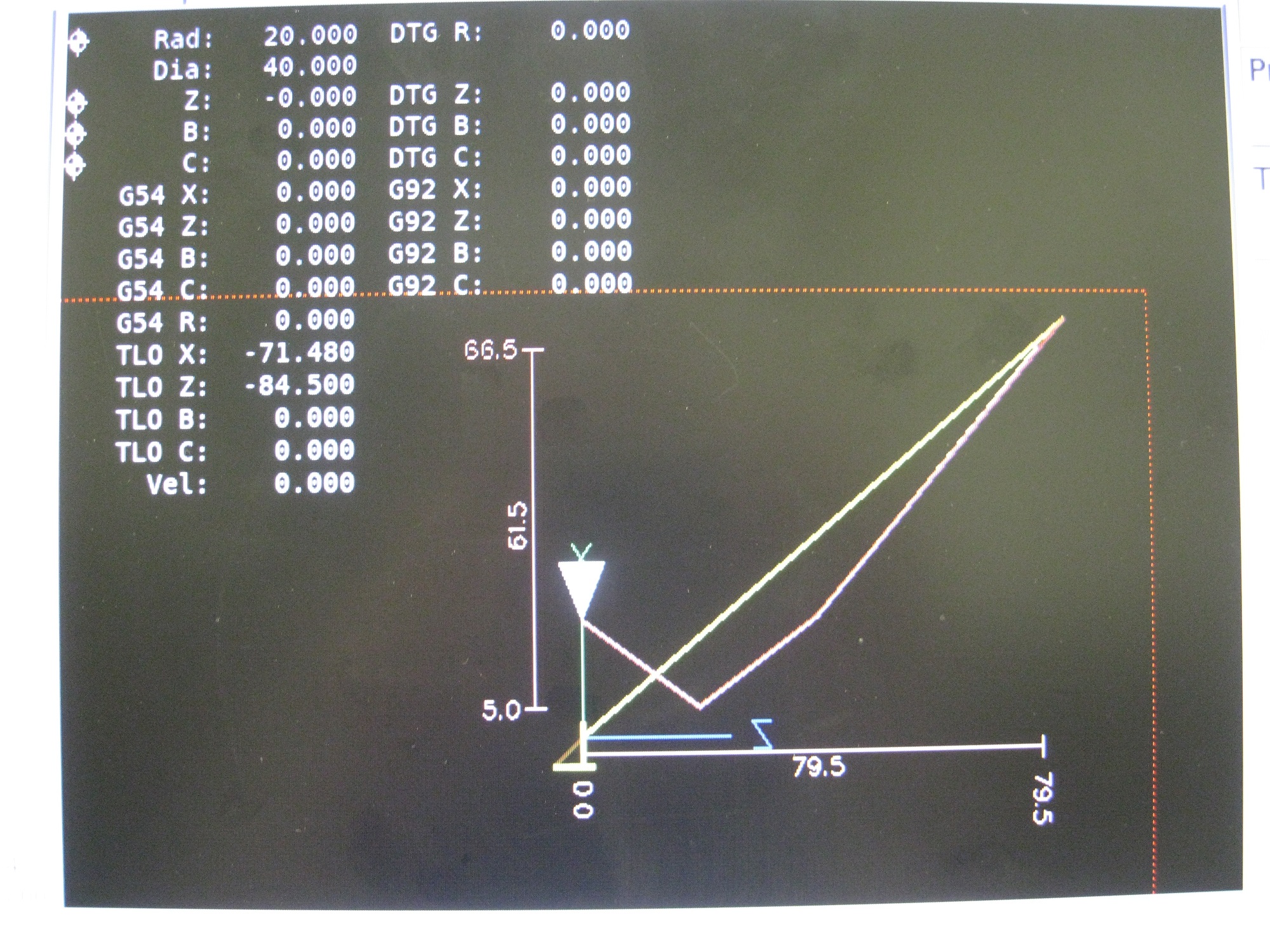
I load the Gcode file again: - display Becomes:
(271)

The new Z offset is in place..
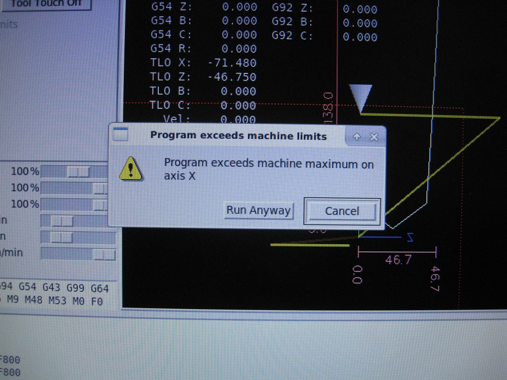
When I try to step ( or run) I have a limits error.
(272)
(273)
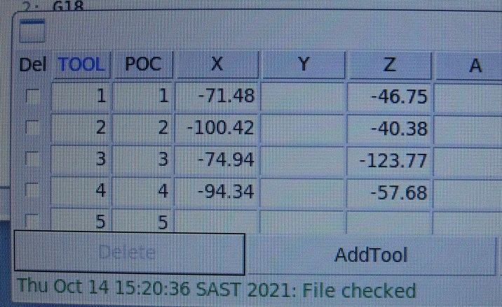
Then I exit Lcnc again, re-load it, Home all, load the Gocde file again.
Now the Tool offsets are as they were in the last failed run.
I then run again and everything works!!!!!
(276)
(277)

What is going on????
Nothing was out of limits in the failed run at all.
Axes were well away from software axis limits, hardware limit/home sensors, etc.
Attachments:
Please Log in or Create an account to join the conversation.
- NoJo
- Offline
- Elite Member
-
- Posts: 180
- Thank you received: 43
Please....
Please Log in or Create an account to join the conversation.
- andypugh
-

- Offline
- Moderator
-

- Posts: 19875
- Thank you received: 4642
You should do coordinate system touch-off. (G54, typically)
Here is what I do.
Tool 1 is a conventional turning/facing tool. I maintain offsets of zero in X and Y for that tool. It is my reference tool, and all other tool offsets are relative to that tool.
I load that tool and touch off the coordinate system Z to a convenient place on the workpiece.
If the machine has lost position, then I set the X of the working coodinate system (G54) approximately to the workpiece (this step is not normally necessary)
I typically face-off the stock at Z=0 at this point.
I then generally take a test cut on diameter or stop a bit short of final dimension, and measure the diameter, then set the X value in G54 (this accounts for work and tool deflection for the work at hand)
If I need to use a different tool, then that will often already have the correct offsets relative to tool 0 in the tool table. If I need to tweak Z or X then _that_ is a tool touch-off.
Note that if the tool table offsets are correct then I can touch-off the coordinate origin using any tool, it does not have to be the reference tool that is used to set the working coordinate system.
Please Log in or Create an account to join the conversation.
- NoJo
- Offline
- Elite Member
-
- Posts: 180
- Thank you received: 43
This should really be a simple concept and I have been struggling. Unfortunately the Linuxcnc docs on the subject are really misleading and dated - I never found the 'tool-table' selection button when clicking on the tool-table select button - likewise the docs don't mention the tool-touch-off button, so impossible to follow the process. Googling does not help as it seems most others are as confused and find their own way of doing the job, all different..
Nowhere is it described how these now new offsets actually get into the tool table either. I sometimes see my new offsets in the table, sometimes it's old ones and the tool does not go where I think it should...
Also confounding matters is the rather loose use of terms such as - coordinate system, working coordinate system, G54 system, etc...For the initiated that may mean the same thing, but not for neophytes...
There are two buttons on AXIS - Touch off and Tool touch off, and these seem to be referred to in mixed manner, mostly never by the button's name, but by inference , eg, 'G54 system'....very confusing sometimes.
I have tried to distill the process down to something simple, if only it would work every time..
There are two issues - one is setting the master tool and then the rest of the tools referenced to the master, the second is setting a new workpiece zero when starting a new job with those tools.
This all In AXIS GUI
Master tool setup:
M6 T1 G43
Jog tool to workpiece zero in Z ( maybe machine the surface flat, etc, etc)
Select Z axis
click Tool_touch_off and enter 0.0
click Touch_off, select P1-54, and enter 0,0
Then do the same for X,
Select X axis, jog tool to diameter, and do Tool_Touch_off and Touch_off with G54 and enter the diameter as measured.
Rest of tools Setup:
M6 T2 G43
Jog tool to workpiece zero in Z, as above.
Select Z axis
click Tool_Touch_off and enter 0.0
DO NOT DO [TOUCH_OFF]
then jog tool to X diameter position
select X axis
click Tool_touch_off and enter diameter
DO NOT DO [TOUCH_OFF]
To get the correct co-ords in the tooltable I do this:
After each [Touch-off or Tool_touch_off] I click on ReRead and ReLoad table, and then SAVE FILE in the tool table.
This tool table thing is a hack - I only get things to work and store the correct coords by doing this but it is messy and undefined!
Then to start on a new workpiece I need to zero a tool in Z on the workpiece somewhere.
I use the master tool,
M6 T1 G43
jog it to a Z start position on the workpiece.
Select Z axis
click Touch_off WITH P1=CURRENT ( NOT G54) and enter 0,0
Is all this correct???
Some statements in your post that I do not understand:
If the machine has lost position, then I set the X of the working coodinate system (G54) approximately to the workpiece (this step is not normally necessary)
What do you mean by 'lost position? What position? Home?, G53? G54? and lost how??
And what do you mean by and how do you set - X of the working coodinate system (G54) approximately to the workpiece ?
Where do you set this 'X' ? In the tool table? with G10? and why approximately? Approximate implies to me that we are somewhere near but how near should it be, or what is constraining how near or far can we be??
Also:
Note that if the tool table offsets are correct then I can touch-off the coordinate origin using any tool, it does not have to be the reference tool that is used to set the working coordinate system.
I guess my tool table offset setting method as described above is not correct then , since if I zero any other than master tool on a new workpiece Z, ( as above) the tools do not end up in the correct reference positions thereafter.
I wish for the GUI and procedure as in PathPilot - that is so clean and intuitive...
Please set me straight!
BTW, am running V2.9 with it's Switchkins, and the Polar Interpolation mode is working very well. G12.1 / G13.1 remap is in and everything is running so we have a C_Axis/Live tool Lathe that can machine odd things on the end of a shaft..Maybe this should be considered for addition to Lcnc/lathe one day..
Please Log in or Create an account to join the conversation.
- andypugh
-
- Offline
- Moderator
-
- Posts: 19875
- Thank you received: 4642
No, that sets the tool offset such that the current position is zero. You don't want that for the master tool, you want a tool offset of zero in the tool table. Either edit the tool table or MDI "G10 L1 P1 X0 Z0".This all In AXIS GUI
Master tool setup:
M6 T1 G43
Jog tool to workpiece zero in Z ( maybe machine the surface flat, etc, etc)
Select Z axis
click Tool_touch_off and enter 0.0
The touch-off buttons basically perform G10 commands behind the scenes, so it is worth knowing what they do:
linuxcnc.org/docs/2.8/html/gcode/g-code.html#gcode:g10-l1
Yes.click Touch_off, select P1-54, and enter 0,0
Then do the same for X,
Select X axis, jog tool to diameter, and do Tool_Touch_off and Touch_off with G54 and enter the diameter as measured.
Yes.Rest of tools Setup:
M6 T2 G43
Jog tool to workpiece zero in Z, as above.
Select Z axis
click Tool_Touch_off and enter 0.0
DO NOT DO [TOUCH_OFF]
then jog tool to X diameter position
select X axis
click Tool_touch_off and enter diameter
DO NOT DO [TOUCH_OFF]
Yes. Though I rarely use anything but G54. I an see the value in using all the coordinate systems for different chucks etc, but I don't botherThen to start on a new workpiece I need to zero a tool in Z on the workpiece somewhere.
I use the master tool,
M6 T1 G43
jog it to a Z start position on the workpiece.
Select Z axis
click Touch_off WITH P1=CURRENT ( NOT G54) and enter 0,0
Is all this correct???
")
My lathe has resolvers which are single-turn absolute. I have cobbled together a system witha position.txt file to give me true absolute position. But if the machine doesn't shut down normally this file does not get saved and my positions are wrong.What do you mean by 'lost position? What position? Home?, G53? G54? and lost how??
This is unlikely to affect you.
Using "touch off". I jog close to a workpiece of known diameter and touch-off to that diameter. But that is only approximate as that won't be the exact diameter turned at that X position.And what do you mean by and how do you set - X of the working coodinate system (G54) approximately to the workpiece ?
Where do you set this 'X' ? In the tool table? with G10? and why approximately? Approximate implies to me that we are somewhere near but how near should it be, or what is constraining how near or far can we be??
I then take a test cut to get an accurate touch-off.
Please Log in or Create an account to join the conversation.
- NoJo
- Offline
- Elite Member
-
- Posts: 180
- Thank you received: 43
Master tool setup:
M6 T1 G43
Jog tool to workpiece zero in Z ( maybe machine the surface flat, etc, etc)
Select Z axis
click Tool_touch_off and enter 0.0
No, that sets the tool offset such that the current position is zero. You don't want that for the master tool, you want a tool offset of zero in the tool table. Either edit the tool table or MDI "G10 L1 P1 X0 Z0".
I did it that way after I found this video on the forum:
(Page down a bit)
Tool Offset video
Is what he did for Tool-1 - at the start - his master tool - then incorrect?
So I want the Z offset for tool 1 to be 0.0 in the tooltable - correct?
I will try this again tomorrow and hope I click.
I am unsure of why you did this:
Why do you do the initial touch off?Using "touch off". I jog close to a workpiece of known diameter and touch-off to that diameter. But that is only approximate as that won't be the exact diameter turned at that X position.
I then take a test cut to get an accurate touch-off.
Is this different from just jogging the tool tip to where it needs to be, line it up for the fine cut, take the cut and then touch_off?
Please Log in or Create an account to join the conversation.
- NoJo
- Offline
- Elite Member
-
- Posts: 180
- Thank you received: 43
I still worry about the variety of propagated methods though - are they incorrect, invalid or also 'workable' alternatives, esp the method in that video for the master/reference tool.
The way I did it left the G54 X and Z coords in AXIS DRO set to 0.0 with a tool offset for X and Z in the tooltable for master tool.
Your way shows offset coords in the G54 X and Z coords in DRO, and tool table is X0 Z0 for ref tool...
I have not found reference to what the convention of approach should be, at least not any description or doc that I could understand..
I would like to have a definitive method that is 'standard' and can stick, since it has serious implications upstream in our Polar Interpolation kinetics - this was working with my 'method' of tool offset establishment since we used the tool-table offset values in the Polar Interpolation for position reference, etc.
I have to see now how to get the same result with the values in the G54 (DRO) values, if those params are accessible..
Please Log in or Create an account to join the conversation.
- Other Stuff
- Show Your Stuff
- Developments on my Home built 5C CNC Lathe - new spindle and progress on the ATC