Retrofit of Precix 5x10 CNC
- randypetersen
-
 Topic Author
- Offline
- Premium Member
-

- Posts: 136
- Thank you received: 15
I updated my wiring diagram per PCW's recommendation for the drive interface. I also took a guess on the encoder interface with the details I got from Magtronic. Hopefully someone can tell me if it make sense or not.
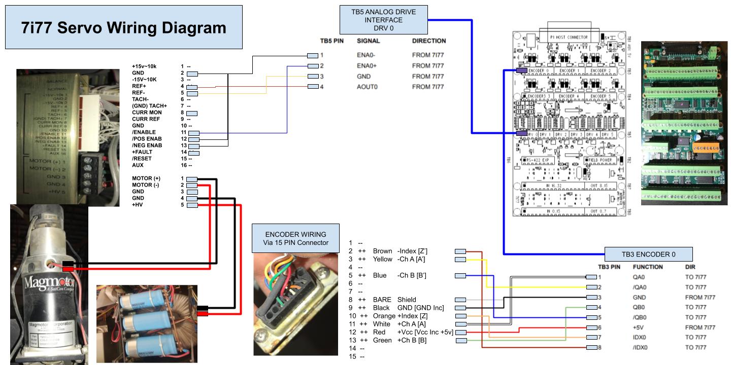
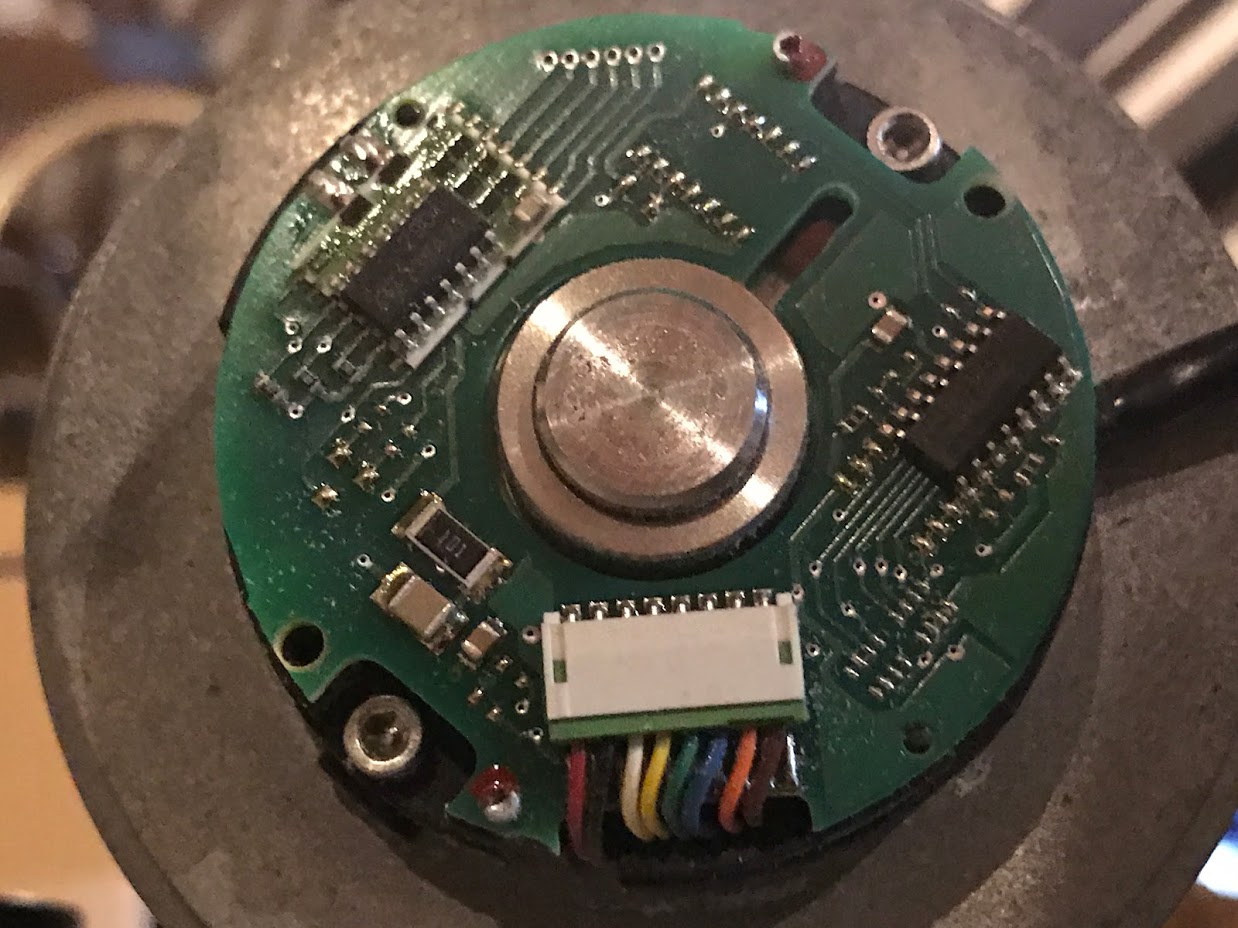
I took off the CAP of the encoder and would have to start to take it apart further to find details PCW mentioned.
I am thinking with the manual I found and the drawing Magtronic sent I can be fairly confident in the wiring, what do you think?
Anyone want to see more pictures (why I don't know) can see them here:
photos.app.goo.gl/wBgjA9fuxgXsEZX96
Attachments:
Please Log in or Create an account to join the conversation.
- randypetersen
-
Topic Author
- Offline
- Premium Member
-
- Posts: 136
- Thank you received: 15
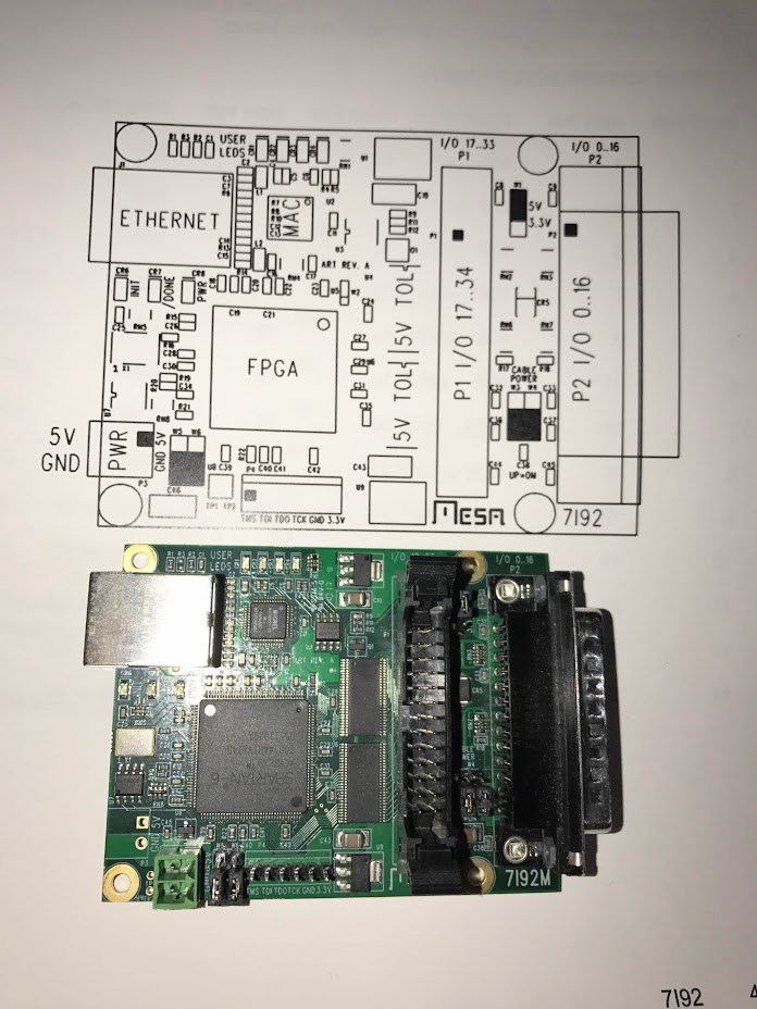
I went ahead and stopped supplying the 5V from the 7i92 by changing jumpers W3 and W4 to the down position. Like they were by default. On the 7i77 I put W5 to the right hand position. I went through it several times to make sure I did it right. Everything was working before when the 7i92 supplied the 5v. Turned it on to make sure I was getting a PING and I got smoke coming from 7i77. Disconnected the 7i92 and powered it by itself and it appears to be working fine, still responded to a ping, however. I checked pins 22/23/24/25 and it was still supplying 5V to those pins.
I kept thinking I did it wrong, but ethernet port on the left W3 and W4 down and still it supplies 5v, what in the heck did I do wrong and what did I fry, I can't afford another one of these 7i92 7i77 units. Can I switch the 7i77 back to W5 right and let the 7i92 supply power?
This really bummed me out, I really wanted to take things slow because I can't afford a mistake and this happens.
Checking the 7i92 not connected to anything, maybe I had the pin wrong? does it supply 5v on other pins even with w3 & w4 down?
I should have left it alone, but when PCW said:
I didn't like the "Probably OK" bit...supplying 7I77 5V from FPGA card is not recommended with a 5I25/7I77 due to drop in the connecting cable, but with a directly connected 7I92M Its probably OK.
Thanks for any help,
Randy
Attachments:
Please Log in or Create an account to join the conversation.
- PCW
-

- Offline
- Moderator
-

- Posts: 17929
- Thank you received: 5253
If you made a jumper mistake and used a non-current limited 5V power supply,
you could have caused an open somewhere in the cable power circuitry
( it may also be the you are not looking at the correct pins, all I/O pins will read 5V
if the 7I92 is not communicating with LinuxCNC )
As a general rule when first setting up things you should use a current limited power supply
so a wrong connection cannot cause damage. Never use a PC power supply for this as
they can often supply 30A to 50A which can destroy PCBs if a mistake is made.
A very easy current limited 5V supply can be made from a USB cable with the small end
cut of and just the red ( +5 ) and black ( GND ) wires used.
What smoked on the 7I77? if it was something other than W5, it may be another issue.
(I would expect W5 to overheat if the jumpers were wrong and high current 5V was applied to the 7I77)
Please Log in or Create an account to join the conversation.
- randypetersen
-
Topic Author
- Offline
- Premium Member
-
- Posts: 136
- Thank you received: 15
Well I was using a PC power supply, so that must have done it.I mentioned that in a post, and was hoping someone would catch me making a (apparently) stupid mistake like that. It always read about 5.05v to 5.1v on my meter. I understand not current limited...
Pin W3 and W4 were definitely in the down position, I made sure they were before applying power. Tripple checked it, because when i initially read the manual, I read the warning and didn't want to get that wrong. When it smoked I figured I did it upside down or something, but when I took it out I placed it right by the manual diagram.
Oh, ok, yes, probably because it wasn't communication with linuxCNC so that's why i was reading 5v...
Since this unit will be 12 or 15 ft away from the computer I guess I will buy an extra long USB cable to supply power to the 7i92, should I use another usb cable to supply 7i77? and you are saying from the computer's USB port to the 7i92 and 7i77 power connections.
Yes, the W5 smoked for sure, and I thought someplace towards the center too, but couldn't see any damage from a quick look.
How should I proceed?
I will get some extra long USB cables to supply power.
Power up 7i92 and make sure it's connected to LinuxCNC then check I/O pins for 5v?
Please Log in or Create an account to join the conversation.
- PCW
-
- Offline
- Moderator
-
- Posts: 17929
- Thank you received: 5253
I would go back to you original settings (7I92 W4 UP 7I77 W5 LEFT)
and power temporarily with a USB cable and see if everything is OK
(after replacing W5)
I suggested a USB cable for testing but its not the best for operation.
for operation I would use a 1A or so 5V DIN rail supply or similar
(to maintain electrical isolation of the 7I77 encoder and Analog section from the PC)
Please Log in or Create an account to join the conversation.
- randypetersen
-
Topic Author
- Offline
- Premium Member
-
- Posts: 136
- Thank you received: 15
Powered the 7i92 (like it was powered and working before) this time with a USB cable from the computer and the 7i92 lit up, but the connected 7i77 didn't show any signs of life. Checked everything several times and was about to give up. Just for the heck of it I replaced the jumpers on the 7i92 and the 7i77 had some lights come on.
LinuxCNC still didn't open, but the log did say it found the 7i92. I ran out of time, but will dig more into it tomorrow.
Please Log in or Create an account to join the conversation.
- randypetersen
-
Topic Author
- Offline
- Premium Member
-
- Posts: 136
- Thank you received: 15
I am really careful with this board, and if it's still OK, I don't want to jeopardize anything going forward.
Thanks PCW for the help, and thanks for anyone's input!
Please Log in or Create an account to join the conversation.
- PCW
-
- Offline
- Moderator
-
- Posts: 17929
- Thank you received: 5253
( only 400 mA or so is needed at for the 5V and less than 100 mA for the 12/24V field voltage)
The laptop supply should be OK for the field voltage, just make sure you have the polarity correct
Please Log in or Create an account to join the conversation.
- randypetersen
-
Topic Author
- Offline
- Premium Member
-
- Posts: 136
- Thank you received: 15
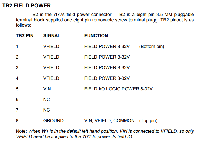
Once I do get a power supply and test it, since W1 is in it's default position, I should just connect the positive to TB2 pin 1 and ground to TB2 pin 8. Why is there 4 different vfield power pins? Do they power different input and output pins? Just curious.
Thanks!
Attachments:
Please Log in or Create an account to join the conversation.
- PCW
-
- Offline
- Moderator
-
- Posts: 17929
- Thank you received: 5253
For normal low power loads you can just use 1 and 8
Please Log in or Create an account to join the conversation.