Retrofit of Precix 5x10 CNC
- randypetersen
-
 Topic Author
- Offline
- Premium Member
-

- Posts: 136
- Thank you received: 15
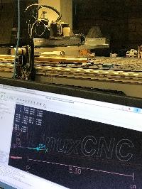
Took some time, but I got it installed and back to where I was before the move. Cool thing is that I have internet access, so I can hopefully respond faster!
I am re-running PNCCONF now that I have my X-Y-Z Axis connected (encoder and driver). I got en error when I first tried to do axis testing about "kernel-version" but got that resolved, however I can't seem to get any movement from my axis. I checked voltage on 7i77 and have 5v (4.6v) on pin 1/2 so it should be enabling my driver, however I am not getting any voltage on pin 3 and 4 while jogging. Should I? Power supply is putting out it's 51V to the drivers, but nothing from drivers to motor. I got a power supply powering the field I/O which is about 12V. (Not using a computer power supply, of course)
I get a little confused on the 7i77x2 firmware, should I choose 6 encoders and 6 PWM generators? in PNCconf?
Do you I think I failed on the 7i92 firmware flashing?
Thanks for any input!
Please Log in or Create an account to join the conversation.
- PCW
-

- Away
- Moderator
-

- Posts: 17989
- Thank you received: 5281
Pins 1/2 on TB5 should be connected when enabled or open when disabled
(they do no output a voltage)
Are the drives enabled? (motors on velocity mode drives will resist applied torque and likely drift slowly)
posting your current hal and ini files will help debugging
Please Log in or Create an account to join the conversation.
- randypetersen
-
Topic Author
- Offline
- Premium Member
-
- Posts: 136
- Thank you received: 15
Oh, ok, I misunderstood on the pins 1/2 I will check for connectivity.
No, I don't think so, they do not resist, not like when I worked with steppers and applied power to them. I don't think there is any power coming from power supply to motors, so they must not be enabled properly. I will double check wiring.
I will post current HAL and INI files, thanks again PCW! I appreciate it.
Please Log in or Create an account to join the conversation.
- randypetersen
-
Topic Author
- Offline
- Premium Member
-
- Posts: 136
- Thank you received: 15
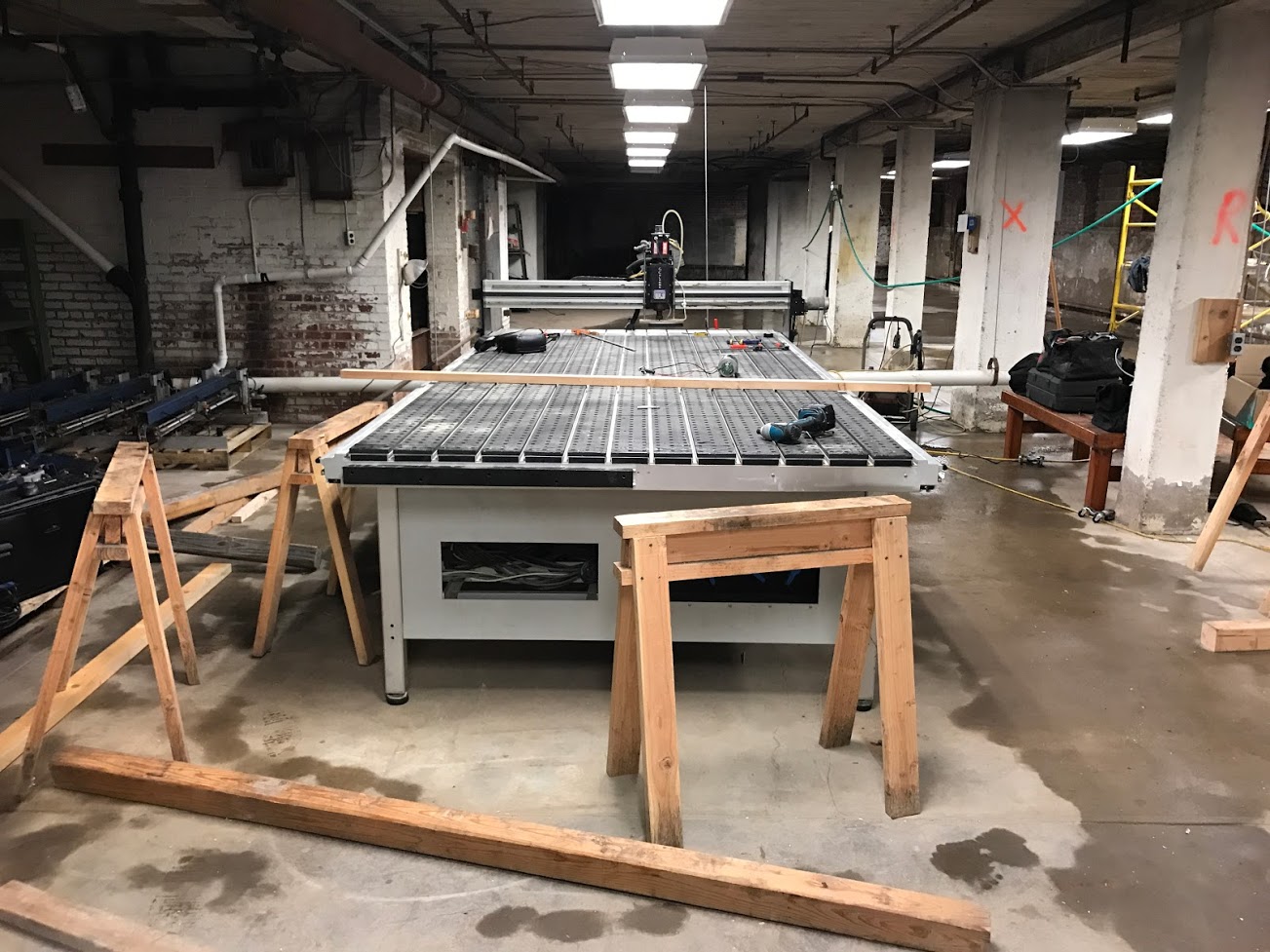
So X and Y are moving and I can look into changing the setting to get those moving properly.
Man, getting that motor to move was very exciting... been a long road to get that far. Probably take you guys a few minutes, but took me a few months... haha...
So I am moving on to my other inputs...
Before I start connecting them, I just want to make sure I have this correct.
For example I have an Estop on the controller box itself.
It's normally closed.
So I would run the field power supply (12V) to one leg of the Estop and the other leg would go to my input pin (0) on the 7i92. The 7i92 would read the voltage as ok, when I hit the e-stop the circuit would open and pin (0) would not get any voltage and the system should stop. Sound right or am I way off?
")
Thanks guys!!!
Please Log in or Create an account to join the conversation.
- PCW
-
- Away
- Moderator
-
- Posts: 17989
- Thank you received: 5281
(TB7 or TB8 pins 1..16)
If you connect a 12V signal anywhere on the 7I92 it will be an ex-7I92...
Please Log in or Create an account to join the conversation.
- randypetersen
-
Topic Author
- Offline
- Premium Member
-
- Posts: 136
- Thank you received: 15
I meant to say 7i77...
So I'm taking the same 12 V that's feeding the field power on the 7i77 Running it through a switch and then into an input pin.
Thanks!! Excited to get those mapped and finished. I have some homework on my Z brake. I think I need to apply power to it to release brake but haven't read about it all yet.
Please Log in or Create an account to join the conversation.
- randypetersen
-
Topic Author
- Offline
- Premium Member
-
- Posts: 136
- Thank you received: 15
Not sure how to share a google video on this forum, but I will try anyway...
I'll bet PCW could have done this in 15minutes with a Mesa card a few paper clips and a stick of chewing gum.
photos.app.goo.gl/dSEzajvjrjT8wcs5A
video - google photos - first X/Y/Z
Before I dig into motor tuning I read where someone was saying these power supply capacitors go bad after about 10 years and should be replaced, and that can mess with the motors. As they work now, they have issues. There is no resistance to movement when powered on, and I need to change speed to get them to move at all. Won't move at all on slow speed.
I was going to start tuning the drivers first, however I figure they must have been working before, and why would they be different now?
It's all good... Still have to wire up limit/homing switches...
Then I got:
Spindle - Power / VFD control
z touch plate
Automatic Tool Changer
Vacuum - Power/Plumb
Misting solenoid
MPG of some sort
Please Log in or Create an account to join the conversation.
- randypetersen
-
Topic Author
- Offline
- Premium Member
-
- Posts: 136
- Thank you received: 15
Spindle Problems:
I was able to purchase the last few things I needed to power up the VFD/SPINDLE.
I got 3 phase running from circuit breaker to fused disconnect and then to VFD and lastly spindle.
I powered up the VFD, not connected to MESA, just for a 'bench' testing. The VFD powered up and looked functional. I tried to get the spindle to move via the control buttons on the VFD, acted like it was locked. I figured it's locked for only input via the control wiring and or needs the enable pin. So I powered it down, and started mapping the wires, currently there are 5 wires from VFD to my controller. After mapping, I fired up the VFD and wanted to check voltage to make sure I had 10V (11.9v) on one wire and 24V (22.7v) on one wire. I got the voltages and went to turn it off and noticed it had an error. "Internal Serial Communications Error" So I thought, maybe my voltage probing screwed something up... So I powered it down, then waiting for 30 seconds... powered it back up and thought it was going to be ok, but it acted like it was not getting a good connection of power and flickered a few times, you could hear a relay clicking and then display went off. Powered it back off and checked all power connections, which were very good. Took cover off and checked components for any signs over overheat conditions. Never had any smoke of any sort. Tried to find some answers online, no luck. Then before I left for the night, I powered it back up. Seemed to power up fine, just like the first time. Anyone ever experienced that? Of course, it's not a LinuxCNC/Mesa problem since it wasn't even connected, just hoped someone might have similar experience with a VFD.
I might have to purchase a new one, if so does anyone have any suggestions for inexpensive VFD to power a 5.5hp spindle (assuming the spindle works)
I'd like to sort out how to connect the VFD to the MESA's spindle ENA5 PWM output.
The VFD has several in/out pins, however there are currently only 5 running to the controller.
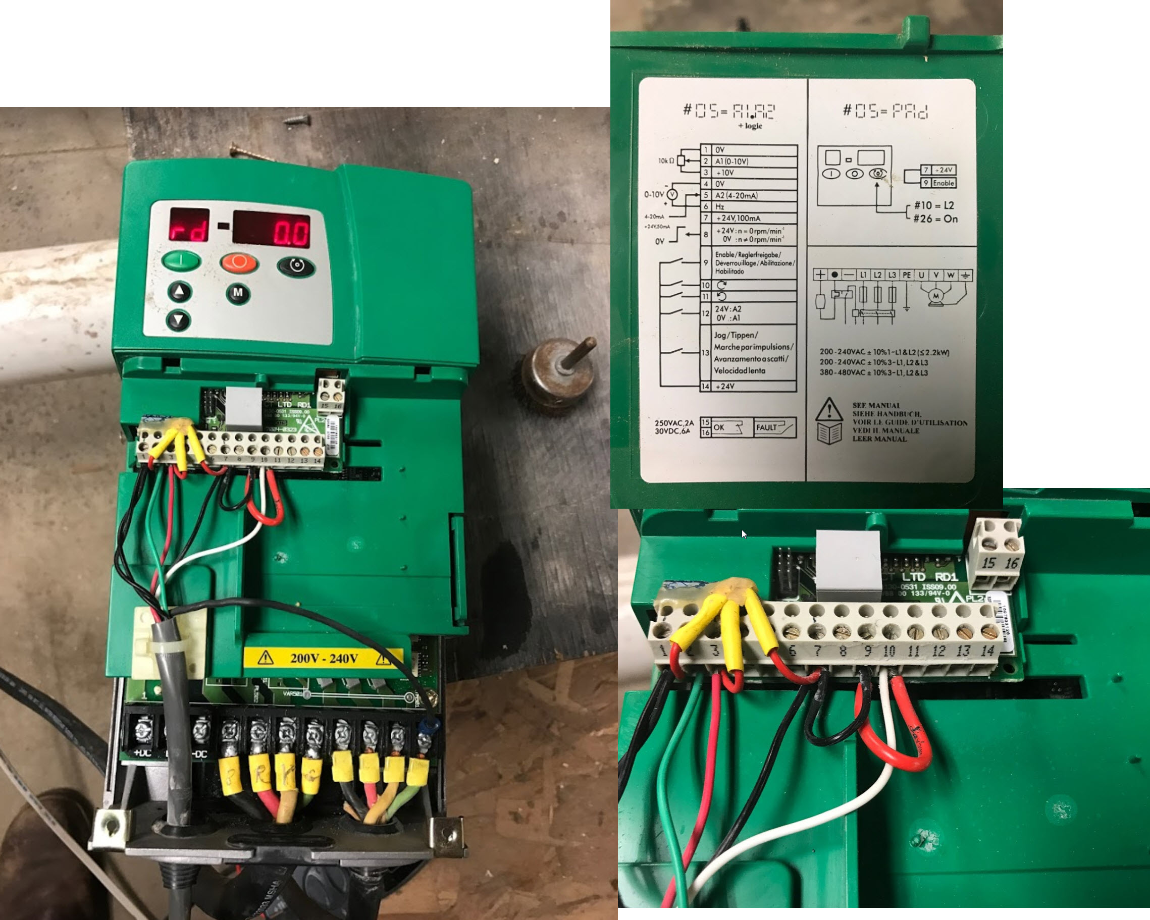
1 -> 0V
2 -> A1 (0-10V) input
3 -> +10V output
7 -> 24V, 100ma output currently
- [Jumpered to 9 -> Enable]
- [Jumpered to 10-> Enable forward] (see pic)
10 -> Enable Forward
from MESA 7i77 Manual
21 ENA5- FROM 7I77
22 ENA5+ FROM 7I77
23 GND FROM 7I77
24 AOUT5 FROM 7I77
Note that the enable outputs are polarized and can be
damaged with reverse polarity. For active high drive enables, ENAN+ should go to the
appropriate positive power supply and ENAN- to the drive enable input. For active low
enable drives, ENAN+ should go the the drive enable and ENAN- to control power ground.
If I had to guess I should remove the jumper from 7 to 9 on VFD so it's not always enabled?
Then connect:
pin 7 (VFD 24V out) to Mesa 22 ENA5+
pin 9 jumpered to pin 10 (VFD Enable and Forward) to Mesa 21 ENA5-
That should enable the VFD and enable "Forward"
Then Connect:
pin 1 (VFD 0V) to Mesa 23 GND
pin 2 (VFD 0-10V input) to Mesa 24 AOUT5
Of course, I am hoping to get some input from the experts before I actually give it a go and see if my VFD behaves better.
Attachments:
Please Log in or Create an account to join the conversation.
- tommylight
-

- Away
- Moderator
-
- Posts: 21738
- Thank you received: 7428
That is as far as i can tell from that picture, and if you do not need reverse.
Please Log in or Create an account to join the conversation.
- randypetersen
-
Topic Author
- Offline
- Premium Member
-
- Posts: 136
- Thank you received: 15
Here is some screenshots from the manual. I am not sure why they didn't want reverse as an option, I can try to sort that out a different day. Having a working spindle (forward only) would be awesome at the moment.
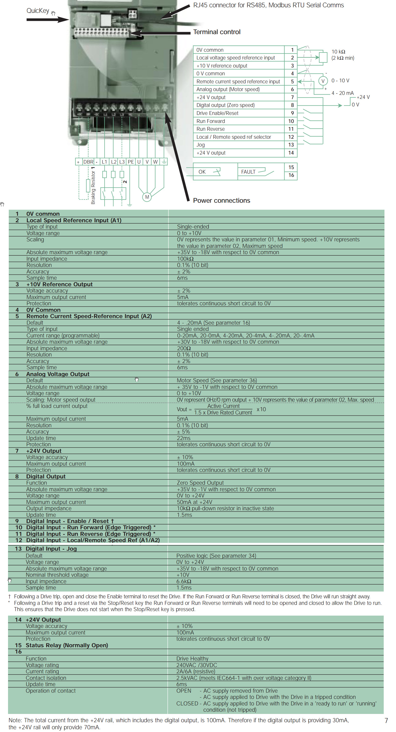
So the Mesa card, outputs it's own 10V PWM signal rather than using the reference output from the VFD.
Attachments:
Please Log in or Create an account to join the conversation.