Retrofit of Precix 5x10 CNC
- randypetersen
-
 Topic Author
- Offline
- Premium Member
-

Less
More
- Posts: 136
- Thank you received: 15
13 Aug 2019 17:04 #142043
by randypetersen
Replied by randypetersen on topic Retrofit of Precix 5x10 CNC
tommylight,
Just realized I am following your servo tuning guide, which is awesome by the way, thanks for that as well!!!
Just realized I am following your servo tuning guide, which is awesome by the way, thanks for that as well!!!
Please Log in or Create an account to join the conversation.
- tommylight
-

- Offline
- Moderator
-

Less
More
- Posts: 21741
- Thank you received: 7430
13 Aug 2019 18:40 #142068
by tommylight
Replied by tommylight on topic Retrofit of Precix 5x10 CNC
It looks like you might need to wire terminal 12 for remote speed controll. Do test without it first and if it enables the drive but does not control speed, just add a short from 24V/100mA to pin 12.
Please Log in or Create an account to join the conversation.
- randypetersen
-
Topic Author
- Offline
- Premium Member
-
Less
More
- Posts: 136
- Thank you received: 15
13 Aug 2019 20:28 - 13 Aug 2019 20:30 #142079
by randypetersen
Replied by randypetersen on topic Retrofit of Precix 5x10 CNC
Thanks again tommylight!
While it was powered off I removed the jumper for enable. I powered it up and got a different message saying inhibited. I manually connected pin 7 to 9/10 and came up ready just like before. I was thinking about holding a batter to pins 1 and 2 to give it some voltage to maybe spin the spindle. Before I could test it I had to answer someone's question and when I got back the display was blank. Flipped the disconnect to off, but it appears like this VFD is dying? Could I be doing something that is causing it to die out?
Checked continuity from VFD to spindle, looks good. Getting ~120V on each leg of the VFD, power to spindle from VFD was like 3v oddly.
Anyone have any thoughts, or is it time for a new one?
Any suggestions for a good/inexpensive/mesa/linuxCNC compatible VFD that can power a 5.5hp spindle would love to hear them.
Well, I will get back to servo tuning...
thanks
Last edit: 13 Aug 2019 20:30 by randypetersen. Reason: added a bit about voltage
Please Log in or Create an account to join the conversation.
- randypetersen
-
Topic Author
- Offline
- Premium Member
-
Less
More
- Posts: 136
- Thank you received: 15
15 Aug 2019 16:45 #142252
by randypetersen
Replied by randypetersen on topic Retrofit of Precix 5x10 CNC
Long story short, found a spark on board of VFD, attempted solder repair, VFD turns on and was responding normally. Who knows for how long. So excited to see the spindle spin, was exhilarating...
Connected it to MESA 7i77 5th PWM connection per previous post.
Ran through PNCCONF just to see if would fire up, and enabled spindle and changed speed, it was spinning!!!
Upped speed, went fast, all good!
Upped speed again, got a trip error on VFD.
AC instantaneous over currnet trip - Insufficient ramp times / phase to phase or phase to earth short circuit at the drive output
I am hoping it's just because I was screwing with it and didn't have parameters correct on control side.
Going to look into setting up the spindle properly in INI/HAL now.
Just wanted to keep you posted, thanks for all the help!!!
Still planning on replacing VFD when I get some funds available.
The following user(s) said Thank You: tommylight
Please Log in or Create an account to join the conversation.
- randypetersen
-
Topic Author
- Offline
- Premium Member
-
Less
More
- Posts: 136
- Thank you received: 15
16 Aug 2019 18:42 #142330
by randypetersen
Replied by randypetersen on topic Retrofit of Precix 5x10 CNC
I should start a new thread, this is mostly not driver board related, but it's so cool to have it all in one thread. See my progress like a dairy of sorts. Hopefully it can help somebody start to finish retrofit a similar machine?
Anyway, I have been trying to 'tune' my spindle with not much success.
I read through tommylights servo tuning, is there something else for setting up a spindle/vfd?
Let me know if anyone knows a good thread to follow, thanks!
Anyway, I have been trying to 'tune' my spindle with not much success.
I read through tommylights servo tuning, is there something else for setting up a spindle/vfd?
Let me know if anyone knows a good thread to follow, thanks!
Please Log in or Create an account to join the conversation.
- PCW
-

- Away
- Moderator
-
Less
More
- Posts: 17990
- Thank you received: 5281
16 Aug 2019 18:59 #142331
by PCW
Replied by PCW on topic Retrofit of Precix 5x10 CNC
Spindle tuning is completely different because:
Velocity mode axis tuning:
command/feeback=position
control output = velocity
Main FF term = FF1 == 1.0 (iff velocity output of PID is scaled in machine units per second)
Main feedback term = P
Spindle tuning
command/feedback=velocity
control output=usually velocity
Main FF term = FF0 ==1.0
Main feedback terms P,I
For spindle tuning, I would start with open loop (FF0 = 1.0 all other terms 0) and then gradually add P to add feedback
Note the the feedback velocity from the encoder is in RPS not RPM so this either needs to be scaled (or use the latest
LinuxCNC master that provides RPM velocity pins from the encoder module)
The following user(s) said Thank You: randypetersen
Please Log in or Create an account to join the conversation.
- Todd Zuercher
-

- Away
- Platinum Member
-

Less
More
- Posts: 4761
- Thank you received: 1463
16 Aug 2019 19:30 #142334
by Todd Zuercher
Replied by Todd Zuercher on topic Retrofit of Precix 5x10 CNC
I would not even call what he needs to do tuning. He just needs to reconfigure the parameters of his VFD for his router spindle after he mucked around with the settings. Most of the big routers I have worked with came with a paper copy of those settings included with the documentation (if you have it. )
The following user(s) said Thank You: randypetersen
Please Log in or Create an account to join the conversation.
- randypetersen
-
Topic Author
- Offline
- Premium Member
-
Less
More
- Posts: 136
- Thank you received: 15
16 Aug 2019 20:11 #142336
by randypetersen
Replied by randypetersen on topic Retrofit of Precix 5x10 CNC
Thanks Todd/PCW,
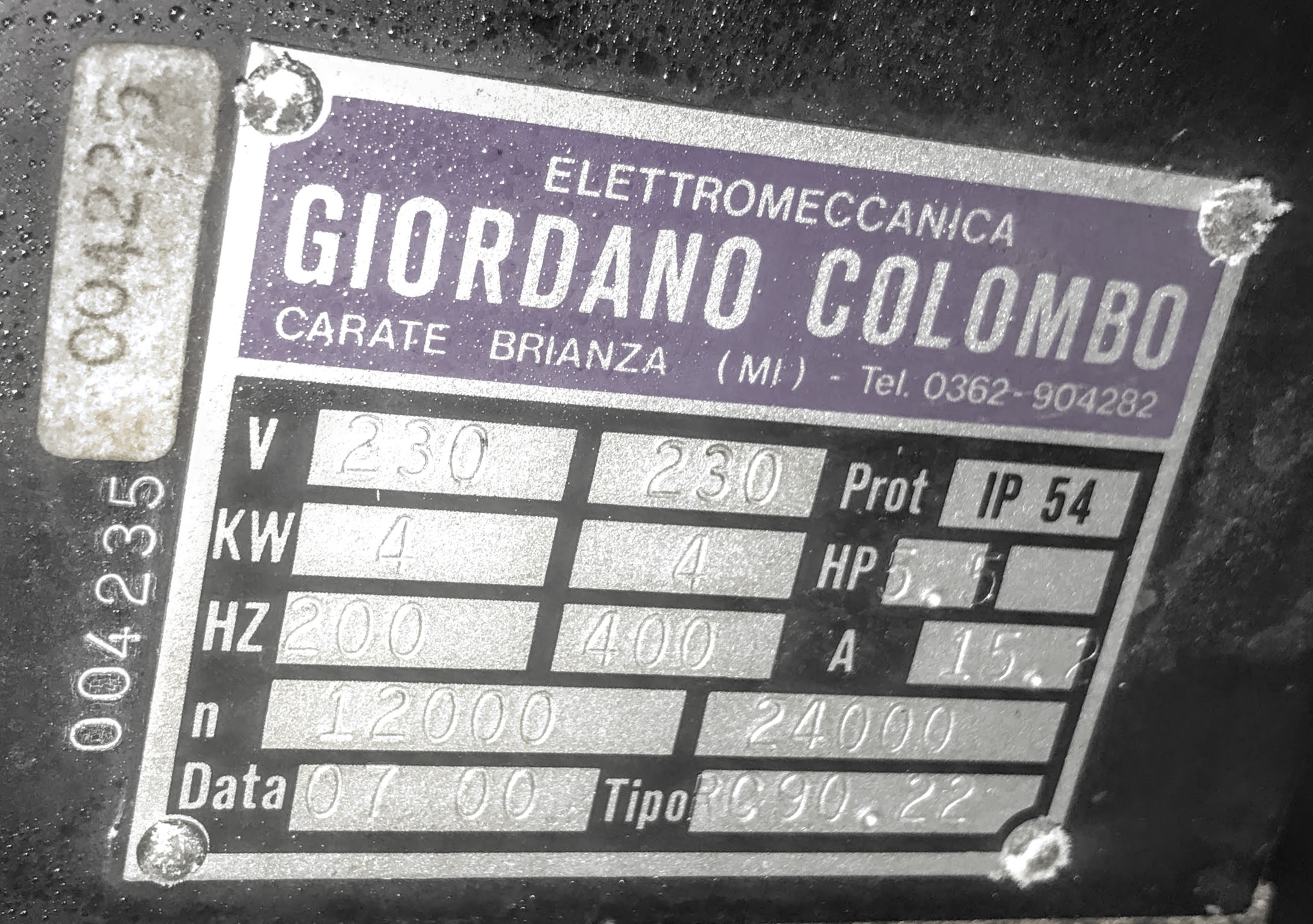
As far as the VFD setting go, I didn't change anything. I did go through them to make sure they weren't defaults. Everything appears to be set for the spindle I have. The items I could see matched the nameplate on the spindle.
I didn't get any paperwork with the spindle, and having difficulty finding a manual.
Colombo Site
That's similar, but this one is 220V RC90.22 I believe,.
I have yet to contact them.
Do you think my problem is with the VFD settings?
Thanks PCW, I guess I figured this spindle setup didn't have feedback of any sort. Shows what I don't know...
I know there is some wires coming from spindle for the ATC, do you think there would be some sort of velocity sensor wire in that bundle? I know there is a wire, that show when the spindle is not moving so you can initiate the ATC.
I figured you set up the VFD, then the MESA card would output 5V and the VFD would translate that to 50% power/speed. and it would just go from there?
Thanks guys!
Attachments:
Please Log in or Create an account to join the conversation.
- randypetersen
-
Topic Author
- Offline
- Premium Member
-
Less
More
- Posts: 136
- Thank you received: 15
17 Aug 2019 00:47 #142353
by randypetersen
Replied by randypetersen on topic Retrofit of Precix 5x10 CNC
apologies Todd,
I thought I would try it just with the VFD which seemed to be working before, well it wasn't. So I was going through the settings on the VFD and the "Rated Speed" was set to "1" and it states if the RPM is greater than 9999 to use a value of "0" so I changed it to 0 and it's behaving much better. Thanks for pointing me in that direction! I must have accidentally changed it when I was changing the input mode from panel to the mesa input.
Now with the spindle again performing properly, I will reconnect it to MESA and try it again.
Thanks again!
Please Log in or Create an account to join the conversation.
- randypetersen
-
Topic Author
- Offline
- Premium Member
-
Less
More
- Posts: 136
- Thank you received: 15
19 Aug 2019 14:41 #142494
by randypetersen
Replied by randypetersen on topic Retrofit of Precix 5x10 CNC
As always thanks for all the help from the forum, clearly I couldn't have done this without you guys.
Been reading about Tool Changers on the forum and the various ways to accomplish this.
Sounds like G-code remap is the easiest method for using a tool changer with a rack system?
I checked out this demo:
sim->axis->remap->racktoolchanger
Would I be able to check my sensors with this method?
Here is some psuedo code I came up when I first started thinking about a tool changer:
probably not even close to the correct ideology.
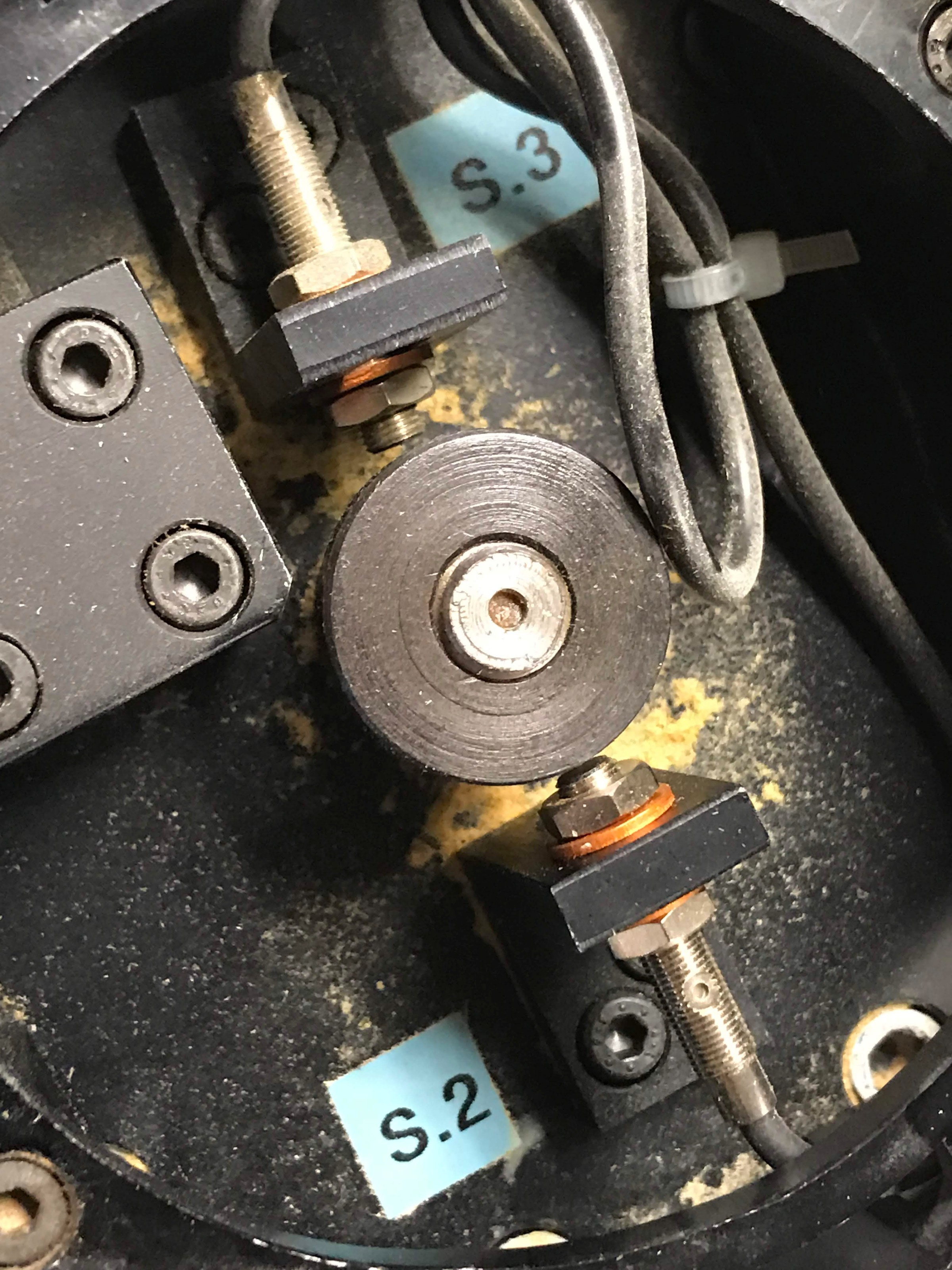
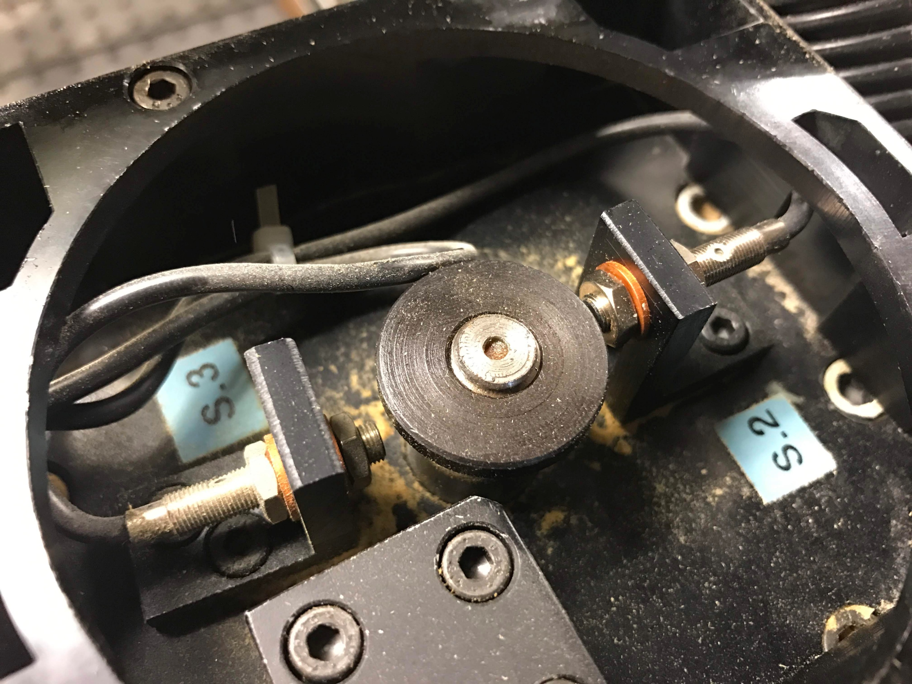
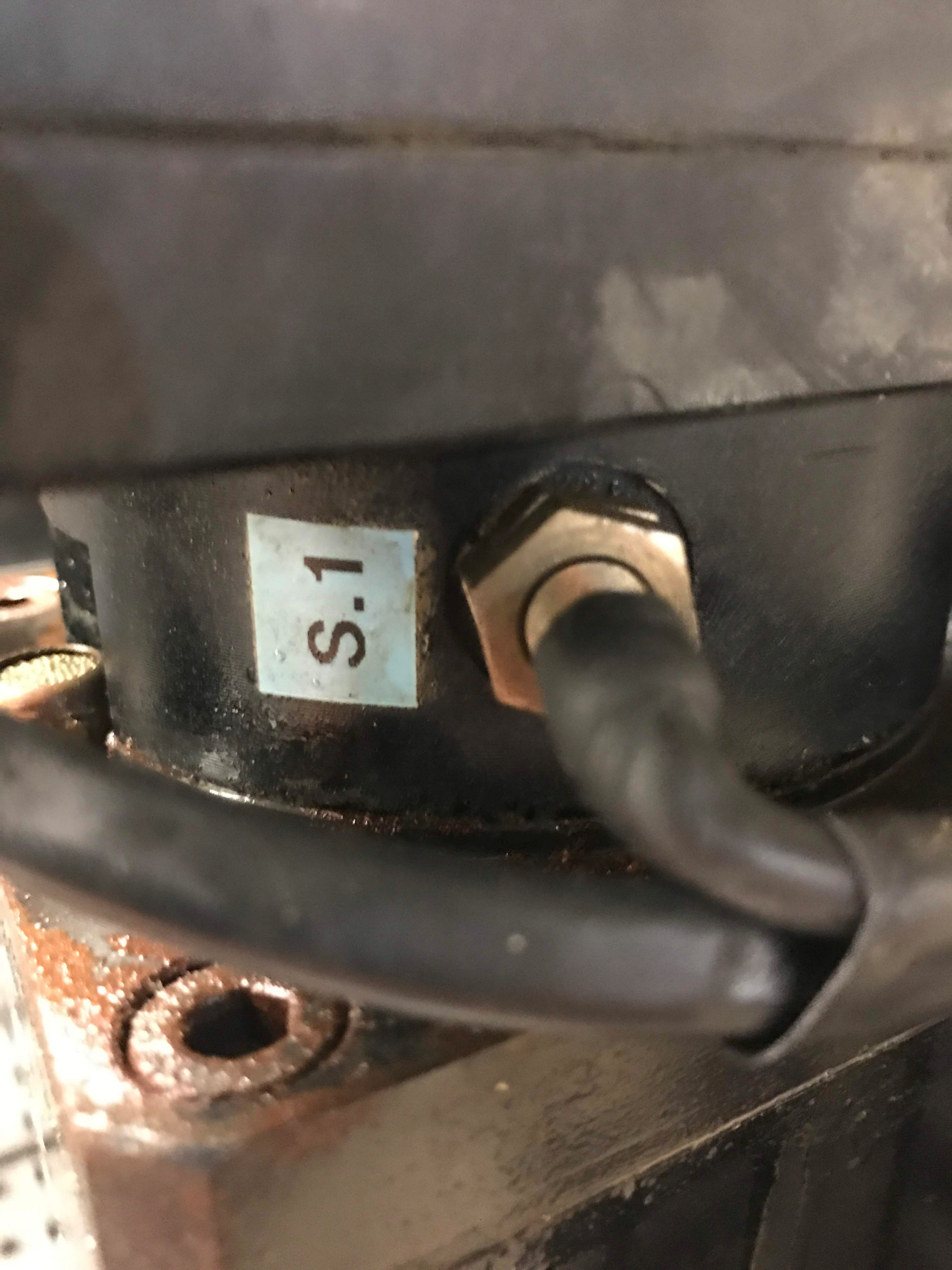
Couldn't find much info on these proximity sensors, I am guessing I would apply my 12V field power to one leg and would normally closed, open when it was active? Anyone got any experience with these colombo sensors. Also having a hard time tracking down the wires, since they appear to be sealed and then shrink tubed so I might have to remove some of the insulation to track down the wire going into my controller.
photos.app.goo.gl/KLZ2nPuCTjw1sw4r9
photos.app.goo.gl/owjzTMWsv3HBuu6U9
Been reading about Tool Changers on the forum and the various ways to accomplish this.
Sounds like G-code remap is the easiest method for using a tool changer with a rack system?
I checked out this demo:
sim->axis->remap->racktoolchanger
Would I be able to check my sensors with this method?
Here is some psuedo code I came up when I first started thinking about a tool changer:
**place tool**
z up to high position (max) - clear work piece/table
x-y to proper position in front of rack (in line of clamps)
z down to proper height in front of rack clamp
make sure spindle is stopped sensor 1
x into tool clamp - sliding tool holder into clamp
solenoid on to release tool holder
make sure S3 active S2 not active
z up to clear tool tool holders
solenoid off
make sure S2 active S3 not active
x back to front of rack

**pickup tool**
z up to high position
x-y to proper position in front of rack
make sure spindle is stopped sensor 1
x over tool holder
solenoid on to release tool holder
make sure S3 active S2 not active
z down to place tool
solenoid off
make sure S2 active S3 not active
x back to front of rack sliding tool off clamp
z up to high position
probably not even close to the correct ideology.
Couldn't find much info on these proximity sensors, I am guessing I would apply my 12V field power to one leg and would normally closed, open when it was active? Anyone got any experience with these colombo sensors. Also having a hard time tracking down the wires, since they appear to be sealed and then shrink tubed so I might have to remove some of the insulation to track down the wire going into my controller.
photos.app.goo.gl/KLZ2nPuCTjw1sw4r9
photos.app.goo.gl/owjzTMWsv3HBuu6U9
Please Log in or Create an account to join the conversation.
Moderators: PCW, jmelson
Time to create page: 0.385 seconds