Emcoturn 120 lathe retrofit
- LutzTD
- Offline
- Elite Member
-

Less
More
- Posts: 216
- Thank you received: 1
03 Dec 2016 23:32 #83639
by LutzTD
Replied by LutzTD on topic Emcoturn 120 lathe retrofit
first pass and right away I am missing this section. Does this generate the stepper pulse?
# ---Chargepump StepGen: 0.25 velocity = 10Khz square wave output---
setp   hm2_5i25.0.stepgen.02.dirsetup        100
setp   hm2_5i25.0.stepgen.02.dirhold         100
setp   hm2_5i25.0.stepgen.02.steplen         100
setp   hm2_5i25.0.stepgen.02.stepspace       100
setp   hm2_5i25.0.stepgen.02.position-scale  10000
setp   hm2_5i25.0.stepgen.02.step_type       2
setp   hm2_5i25.0.stepgen.02.control-type    1
setp   hm2_5i25.0.stepgen.02.maxaccel        0
setp   hm2_5i25.0.stepgen.02.maxvel          0
setp   hm2_5i25.0.stepgen.02.velocity-cmd    0.25
Please Log in or Create an account to join the conversation.
- tome
- Offline
- Premium Member
-

Less
More
- Posts: 116
- Thank you received: 11
03 Dec 2016 23:47 #83641
by tome
No, that section is my chargepump waveform, not related to X/Z stepper motors. You don't need that if you aren't driving a chargepump from the 5i25.
You should only need the sections "AXIS X" and "AXIS Z" from that file.
-Tom
Replied by tome on topic Emcoturn 120 lathe retrofit
first pass and right away I am missing this section. Does this generate the stepper pulse?
# ---Chargepump StepGen: 0.25 velocity = 10Khz square wave output---
setp   hm2_5i25.0.stepgen.02.dirsetup        100
setp   hm2_5i25.0.stepgen.02.dirhold         100
setp   hm2_5i25.0.stepgen.02.steplen         100
setp   hm2_5i25.0.stepgen.02.stepspace       100
setp   hm2_5i25.0.stepgen.02.position-scale  10000
setp   hm2_5i25.0.stepgen.02.step_type       2
setp   hm2_5i25.0.stepgen.02.control-type    1
setp   hm2_5i25.0.stepgen.02.maxaccel        0
setp   hm2_5i25.0.stepgen.02.maxvel          0
setp   hm2_5i25.0.stepgen.02.velocity-cmd    0.25
No, that section is my chargepump waveform, not related to X/Z stepper motors. You don't need that if you aren't driving a chargepump from the 5i25.
You should only need the sections "AXIS X" and "AXIS Z" from that file.
-Tom
Please Log in or Create an account to join the conversation.
- PCW
-

- Offline
- Moderator
-

Less
More
- Posts: 17940
- Thank you received: 5255
03 Dec 2016 23:48 #83642
by PCW
Replied by PCW on topic Emcoturn 120 lathe retrofit
Looks like that is for setting up stepgen2 to generate a square wave output to run a charge pump circuit
( Though the frequency will not be 10 KHz but rather 162.5 Hz,
hm2_5i25.0.stepgen.02.velocity-cmd should be set to 4 to get 10 KHz )
( Though the frequency will not be 10 KHz but rather 162.5 Hz,
hm2_5i25.0.stepgen.02.velocity-cmd should be set to 4 to get 10 KHz )
Please Log in or Create an account to join the conversation.
- andypugh
-

- Away
- Moderator
-
Less
More
- Posts: 19871
- Thank you received: 4640
03 Dec 2016 23:49 #83643
by andypugh
Replied by andypugh on topic Emcoturn 120 lathe retrofit
A useful first stage in working out the stepper wiring will be to figure out which terminals are pairs (ie, the ends of the same winding). You can do this with a multimeter.
Please Log in or Create an account to join the conversation.
- tome
- Offline
- Premium Member
-
Less
More
- Posts: 116
- Thank you received: 11
03 Dec 2016 23:50 #83644
by tome
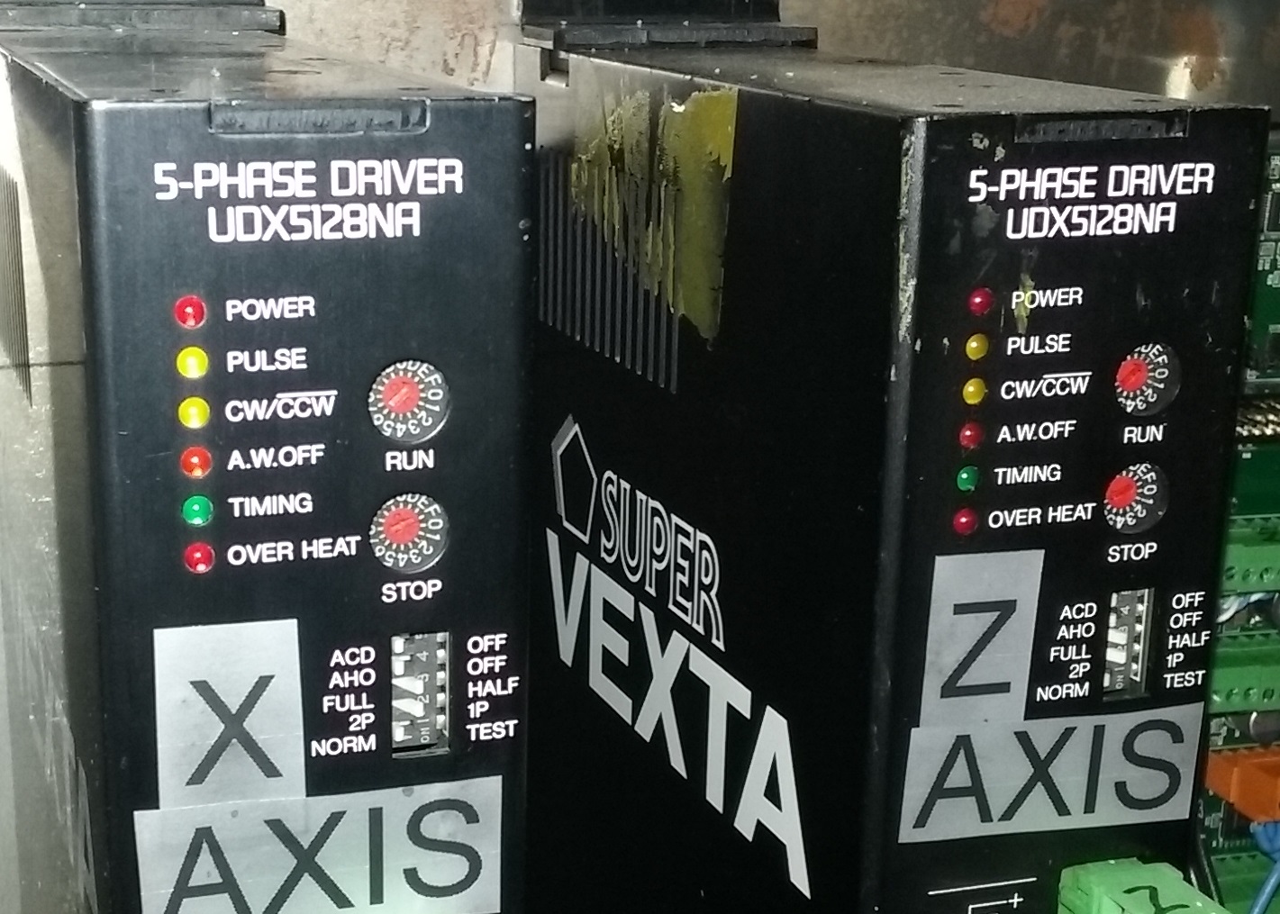
I recall those are a signal from the Vexta if it overheats...? I wired those to an input in order to do something if I see that signal.
It's taken care of in this section (though not tested):
# --- Over Temperature Inputs ---
# --- ** added without testing amp-fault (should cause no X,Z motion if Vexta overheat)
#spindle-overtemp hm2_5i25.0.7i84.0.0.input-17 **see above
net z-axis-overtemp hm2_5i25.0.7i84.0.0.input-19 axis.2.amp-fault-in
net x-axis-overtemp hm2_5i25.0.7i84.0.0.input-20 axis.0.amp-fault-in
# --- End of Over Temperature section----
Replied by tome on topic Emcoturn 120 lathe retrofit
I notice you have wires on the timing, o.heat/com terminals? where do those connect?
I recall those are a signal from the Vexta if it overheats...? I wired those to an input in order to do something if I see that signal.
It's taken care of in this section (though not tested):
# --- Over Temperature Inputs ---
# --- ** added without testing amp-fault (should cause no X,Z motion if Vexta overheat)
#spindle-overtemp hm2_5i25.0.7i84.0.0.input-17 **see above
net z-axis-overtemp hm2_5i25.0.7i84.0.0.input-19 axis.2.amp-fault-in
net x-axis-overtemp hm2_5i25.0.7i84.0.0.input-20 axis.0.amp-fault-in
# --- End of Over Temperature section----
Please Log in or Create an account to join the conversation.
- tome
- Offline
- Premium Member
-
Less
More
- Posts: 116
- Thank you received: 11
04 Dec 2016 00:05 #83645
by tome
First, on my Vexta drive the motor terminals are labeled (from top to bottom) Blue, Red, Orange, Green, Black. Like this picture:
www.artisantg.com/ViewImage.aspx?Image=V...&StockNumber=64142-2
If the numbers in the white squares on your picture correspond to the labeled wire numbers then I would try wiring:
10 and 2 to Blue
5 and 8 to Red
3 and 6 to Orange
1 and 9 to Green
4 and 7 to Black
I believe that is equivalent to the picture I posted above for my wiring.
In terms of the .ini and .hal, the important parts of those configs are in the Axis X and Axis Z sections.
-Tom
Replied by tome on topic Emcoturn 120 lathe retrofit
wow thanx for the files, that is awesome
")
in wire harness for the stepper, the numbered wires do not match the stepper terminal numbers, the picture attached is the way the Emco harness is wired. I rewired the stepper so that the harness wire number matches the stepper terminal number. 1-1,2-2,3-3,4-4,5-5,6-6,7-7,8-8,9-9,0-10. figured that was it but no go. Still just vibrates and doesnt move. I changed the option switches and found I only have 5 where you have 6 switches, but I matched the ones that are there. still no go. I looked at the ini files and it looks like you have more lines for the stepper config and the values are different. I knew mine were wrong so this is expected, I will try to merge the ini files some tonight and give it another shot.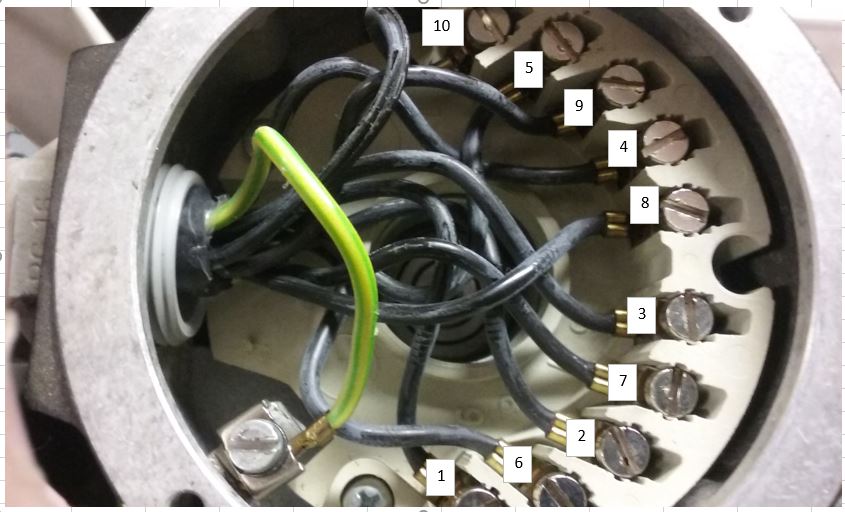
First, on my Vexta drive the motor terminals are labeled (from top to bottom) Blue, Red, Orange, Green, Black. Like this picture:
www.artisantg.com/ViewImage.aspx?Image=V...&StockNumber=64142-2
If the numbers in the white squares on your picture correspond to the labeled wire numbers then I would try wiring:
10 and 2 to Blue
5 and 8 to Red
3 and 6 to Orange
1 and 9 to Green
4 and 7 to Black
I believe that is equivalent to the picture I posted above for my wiring.
In terms of the .ini and .hal, the important parts of those configs are in the Axis X and Axis Z sections.
-Tom
Please Log in or Create an account to join the conversation.
- tome
- Offline
- Premium Member
-
Less
More
- Posts: 116
- Thank you received: 11
04 Dec 2016 00:43 - 04 Dec 2016 00:44 #83646
by tome
Replied by tome on topic Emcoturn 120 lathe retrofit
Below is the relevant diagram from the Oriental Motor forum thread I posted earlier. The numbers 1-9,0 are clockwise around the motor as shown in the bottom right of this image: bgp.nu/~tom/pub/IMG_3890.JPG
The trick is to match the wiring labels which have a sequence of their own...
The trick is to match the wiring labels which have a sequence of their own...
Last edit: 04 Dec 2016 00:44 by tome.
Please Log in or Create an account to join the conversation.
- LutzTD
- Offline
- Elite Member
-
Less
More
- Posts: 216
- Thank you received: 1
04 Dec 2016 01:23 #83647
by LutzTD
Replied by LutzTD on topic Emcoturn 120 lathe retrofit
in looking at the HAL. I see my HAL is setting up a PID "loadrt pid names=pid.x,pid.z,pid.s" (I dont know what a pid is ) then in the axis drive section it calls for the pid
#*******************
# AXIS X
#*******************
setp pid.x.Pgain [AXIS_0]P
setp pid.x.Igain [AXIS_0]I
setp pid.x.Dgain [AXIS_0]D
setp pid.x.bias [AXIS_0]BIAS
setp pid.x.FF0 [AXIS_0]FF0
setp pid.x.FF1 [AXIS_0]FF1
setp pid.x.FF2 [AXIS_0]FF2
setp pid.x.deadband [AXIS_0]DEADBAND
setp pid.x.maxoutput [AXIS_0]MAX_OUTPUT
setp pid.x.error-previous-target true
setp pid.x.maxerror .0005
net x-index-enable <=> pid.x.index-enable
net x-enable => pid.x.enable
net x-pos-cmd => pid.x.command
net x-vel-cmd => pid.x.command-deriv
net x-pos-fb => pid.x.feedback
net x-output => pid.x.output
So I think my entire setup is completely wrong. I assume I can copy your "loadrt" and "addf" section and the axis "setp" sections and get the write stepper control setup?
) then in the axis drive section it calls for the pid#*******************
# AXIS X
#*******************
setp pid.x.Pgain [AXIS_0]P
setp pid.x.Igain [AXIS_0]I
setp pid.x.Dgain [AXIS_0]D
setp pid.x.bias [AXIS_0]BIAS
setp pid.x.FF0 [AXIS_0]FF0
setp pid.x.FF1 [AXIS_0]FF1
setp pid.x.FF2 [AXIS_0]FF2
setp pid.x.deadband [AXIS_0]DEADBAND
setp pid.x.maxoutput [AXIS_0]MAX_OUTPUT
setp pid.x.error-previous-target true
setp pid.x.maxerror .0005
net x-index-enable <=> pid.x.index-enable
net x-enable => pid.x.enable
net x-pos-cmd => pid.x.command
net x-vel-cmd => pid.x.command-deriv
net x-pos-fb => pid.x.feedback
net x-output => pid.x.output
So I think my entire setup is completely wrong. I assume I can copy your "loadrt" and "addf" section and the axis "setp" sections and get the write stepper control setup?
Please Log in or Create an account to join the conversation.
- andypugh
-
- Away
- Moderator
-
Less
More
- Posts: 19871
- Thank you received: 4640
04 Dec 2016 01:30 - 04 Dec 2016 01:31 #83648
by andypugh
en.wikipedia.org/wiki/PID_controller
Mandatory for servo systems, optional for stepper systems.
Replied by andypugh on topic Emcoturn 120 lathe retrofit
PID is a type of feedback controller.in looking at the HAL. I see my HAL is setting up a PID "loadrt pid names=pid.x,pid.z,pid.s" (I dont know what a pid is
en.wikipedia.org/wiki/PID_controller
Mandatory for servo systems, optional for stepper systems.
Not necessarily. PnCConf sets up a PID controller for Mesa card stepper systems because it makes the system less susceptible to servo-thread jitter.So I think my entire setup is completely wrong.
Last edit: 04 Dec 2016 01:31 by andypugh.
Please Log in or Create an account to join the conversation.
- LutzTD
- Offline
- Elite Member
-
Less
More
- Posts: 216
- Thank you received: 1
04 Dec 2016 01:39 #83649
by LutzTD
Replied by LutzTD on topic Emcoturn 120 lathe retrofit
ok thanx, I may just go ahead and drop the pid for the x and z. the spindle is working OK so Im going to leave that. It seems like my issue is in the software driving the axis controllers and motors, so Im going to try to sub in your stuff for the axis control. I figured it was the control, Its in a feedback loop because it jitters even after I try to move it like its hunting.
Please Log in or Create an account to join the conversation.
Time to create page: 0.239 seconds