Emcoturn 120 lathe retrofit
- LutzTD
- Offline
- Elite Member
-

Less
More
- Posts: 216
- Thank you received: 1
25 Jul 2016 16:25 #77996
by LutzTD
Replied by LutzTD on topic Emcoturn 120 lathe retrofit
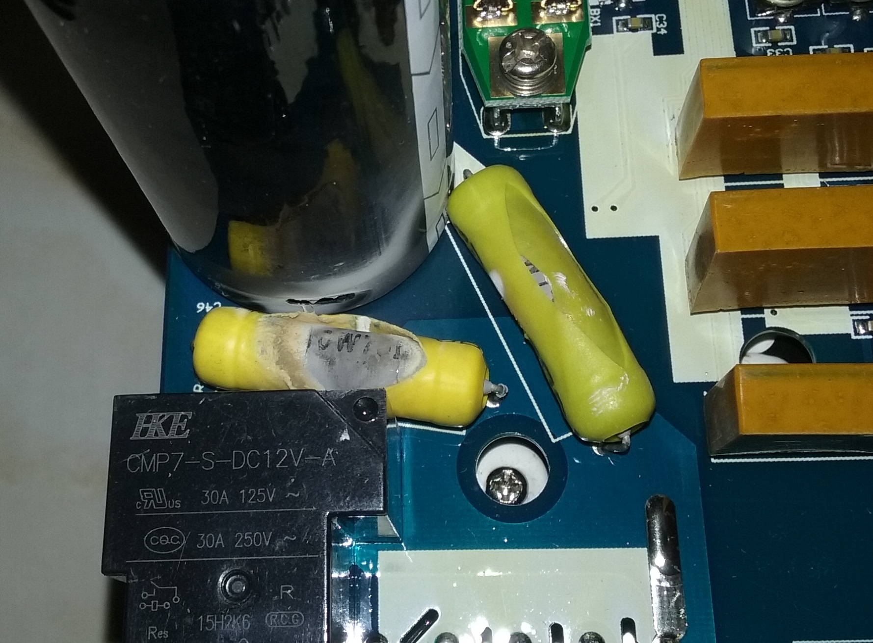
The brake worked once, then a zzzzzzzzz and smoke and that's all folks. Looks like the brake resistors arced. They agreed to refund me half, which was about the same as sending it back and forth to get it fixed. I pulled it apart and maybe I will replace the 2 resistors with something slightly better quality and see if it fixes it. They look like they are both 10W75Ohm, I found some 25W75Ohm replacements for about $15 Either way I ordered a new drive from automation direct. If this one works after the fix Ill save it for a less demanding application.
Please Log in or Create an account to join the conversation.
- Muzzer
- Offline
- Elite Member
-
Less
More
- Posts: 266
- Thank you received: 42
25 Jul 2016 17:29 #78005
by Muzzer
Replied by Muzzer on topic Emcoturn 120 lathe retrofit
Might be wrong but they actually look to me like the soft start (precharge) resistors, next to the main diode bridge and soft start(?) relay. Also, "internal braking resistors" don't sound right to me. If there is no external braking resistor, any deceleration is generally absorbed by the internal (switching) losses. Perhaps I'm wrong.
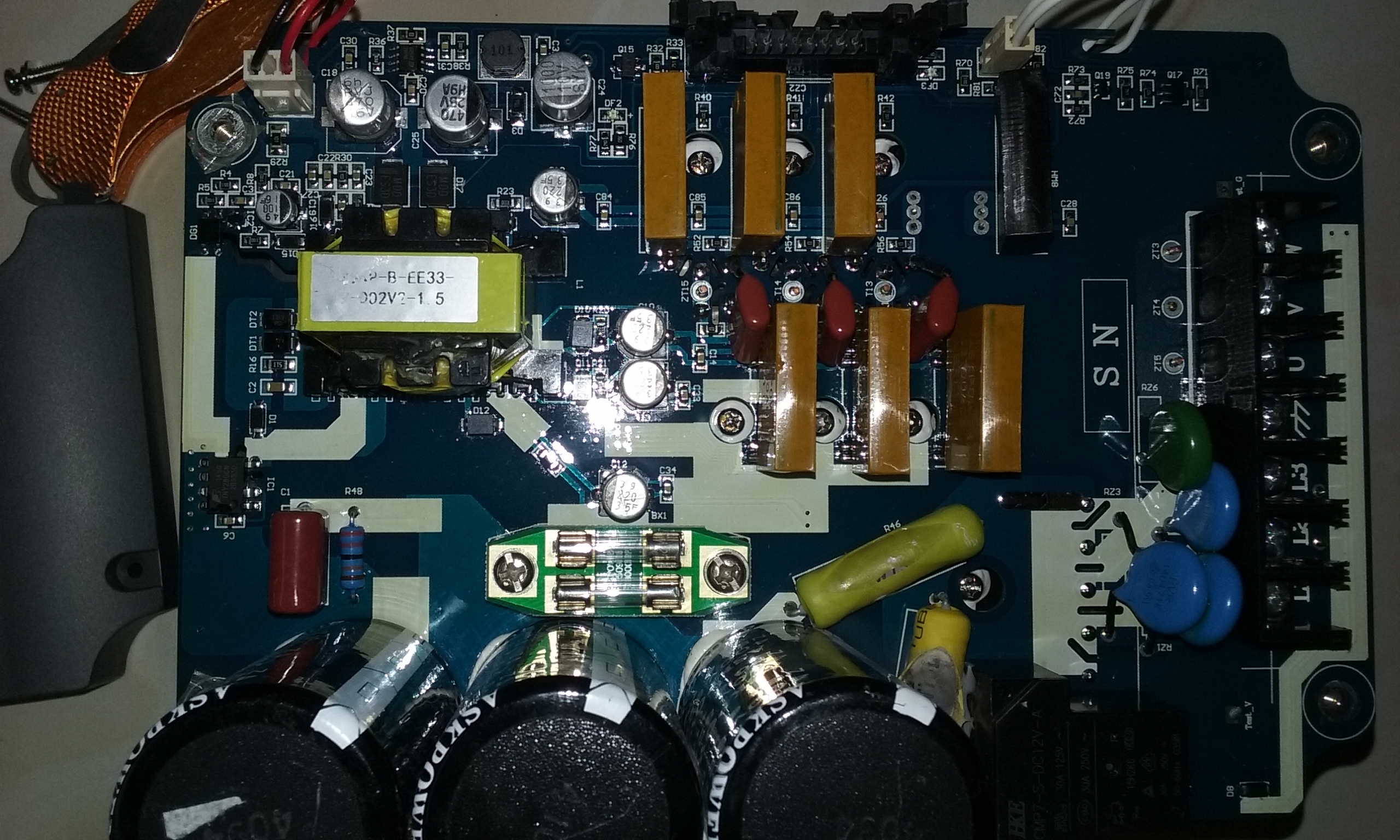
Could you post a slightly more zoomed out photo? If I'm right, the repairs will require more than just a couple of resistors and you are looking at a piece of scrap.
Dunno what VFD you have there but has anyone got a schematic diagram?
Could you post a slightly more zoomed out photo? If I'm right, the repairs will require more than just a couple of resistors and you are looking at a piece of scrap.
Dunno what VFD you have there but has anyone got a schematic diagram?
Please Log in or Create an account to join the conversation.
- jmelson
- Offline
- Moderator
-

Less
More
- Posts: 520
- Thank you received: 126
25 Jul 2016 18:31 #78010
by jmelson
Replied by jmelson on topic Emcoturn 120 lathe retrofit
As Muzzer says, these may be in the precharge circuit. If they fried, it may be one or more of the IGBTs shorted, and since the precharge could not fill the capacitor bank, it just kept trying until the resistors smoked. You might take an ohmmeter reading on each of the motor terminals to the cap bank + and minus to see if any transistors are shorted. You SHOULD get an open-circuit reading.
If these resistors are in parallel to the DC supply, they would pull 11 A, which might be about right for a 5 Hp drive. ***BUT***, there's no way a full braking resistor set would be two tiny resistors on the circuit board. I'm running two 50 W resistors in open air on my 1 Hp drive on my Bridgeport, and two 100 W resistors on my lathe (with 5 HP motor.)
Jon
Please Log in or Create an account to join the conversation.
- LutzTD
- Offline
- Elite Member
-
Less
More
- Posts: 216
- Thank you received: 1
25 Jul 2016 21:55 - 25 Jul 2016 21:57 #78020
by LutzTD
Replied by LutzTD on topic Emcoturn 120 lathe retrofit
yeah thats an ME talking electronics ") . I assumed they were brake resistors. These were really cheap looking, very thin coating of insulation. In fact they sleeved it 2 layers with shrink tubing and it still arced around that. An EE at work told me it was a clearance issue and that if I replace the resistors I should add some insulation barriers to be safe.
. I assumed they were brake resistors. These were really cheap looking, very thin coating of insulation. In fact they sleeved it 2 layers with shrink tubing and it still arced around that. An EE at work told me it was a clearance issue and that if I replace the resistors I should add some insulation barriers to be safe.
I was going to try to replace these, but if there is a trouble shoot step I can do before I fork out for resistors then I would love to save the money. The error code I got was for acceleration not deceleration. I was going to remove the value that the vendor gave me for acceleration but when I turned it on again thats when it smoked.
I left the chassis at work, but Ill take some more pics tomorrow. I do not have and cant get the schematic.
I looked for any other physical signs of damage and saw nothing, but of course the whole thing could be shot internally.
. I assumed they were brake resistors. These were really cheap looking, very thin coating of insulation. In fact they sleeved it 2 layers with shrink tubing and it still arced around that. An EE at work told me it was a clearance issue and that if I replace the resistors I should add some insulation barriers to be safe.I was going to try to replace these, but if there is a trouble shoot step I can do before I fork out for resistors then I would love to save the money. The error code I got was for acceleration not deceleration. I was going to remove the value that the vendor gave me for acceleration but when I turned it on again thats when it smoked.
I left the chassis at work, but Ill take some more pics tomorrow. I do not have and cant get the schematic.
I looked for any other physical signs of damage and saw nothing, but of course the whole thing could be shot internally.
Last edit: 25 Jul 2016 21:57 by LutzTD.
Please Log in or Create an account to join the conversation.
- LutzTD
- Offline
- Elite Member
-
Less
More
- Posts: 216
- Thank you received: 1
25 Jul 2016 22:00 #78021
by LutzTD
Replied by LutzTD on topic Emcoturn 120 lathe retrofit
I did have a bigger picture. just the one.
Please Log in or Create an account to join the conversation.
- Muzzer
- Offline
- Elite Member
-
Less
More
- Posts: 266
- Thank you received: 42
28 Jul 2016 12:20 #78095
by Muzzer
Replied by Muzzer on topic Emcoturn 120 lathe retrofit
I only see six IGBTs there (you would need another one for braking control) and there are no terminals for connecting an external braking resistor. So this drive doesn't look as if it supports use of a braking resistor.
The black relay at the bottom right is the soft start relay and it is clearly not being energised for some reason. It's possible that there is something wrong with it but that seems unlikely. The little transformer wrapped in yellow polyester tape (top left) is the internal PSU for the control circuit. There's a good chance it isn't able to power the relay if one or more of the IGBTs are shot and the associated gate drive circuit(s) are buggered.
It's possible that the damage is restricted to just one IGBT but that would be unusual. You can probably use this to keep a door propped open now. I don't think you've done anything wrong, other than pay good money for it.
Murray
Please Log in or Create an account to join the conversation.
- LutzTD
- Offline
- Elite Member
-
Less
More
- Posts: 216
- Thank you received: 1
28 Jul 2016 12:23 #78096
by LutzTD
Replied by LutzTD on topic Emcoturn 120 lathe retrofit
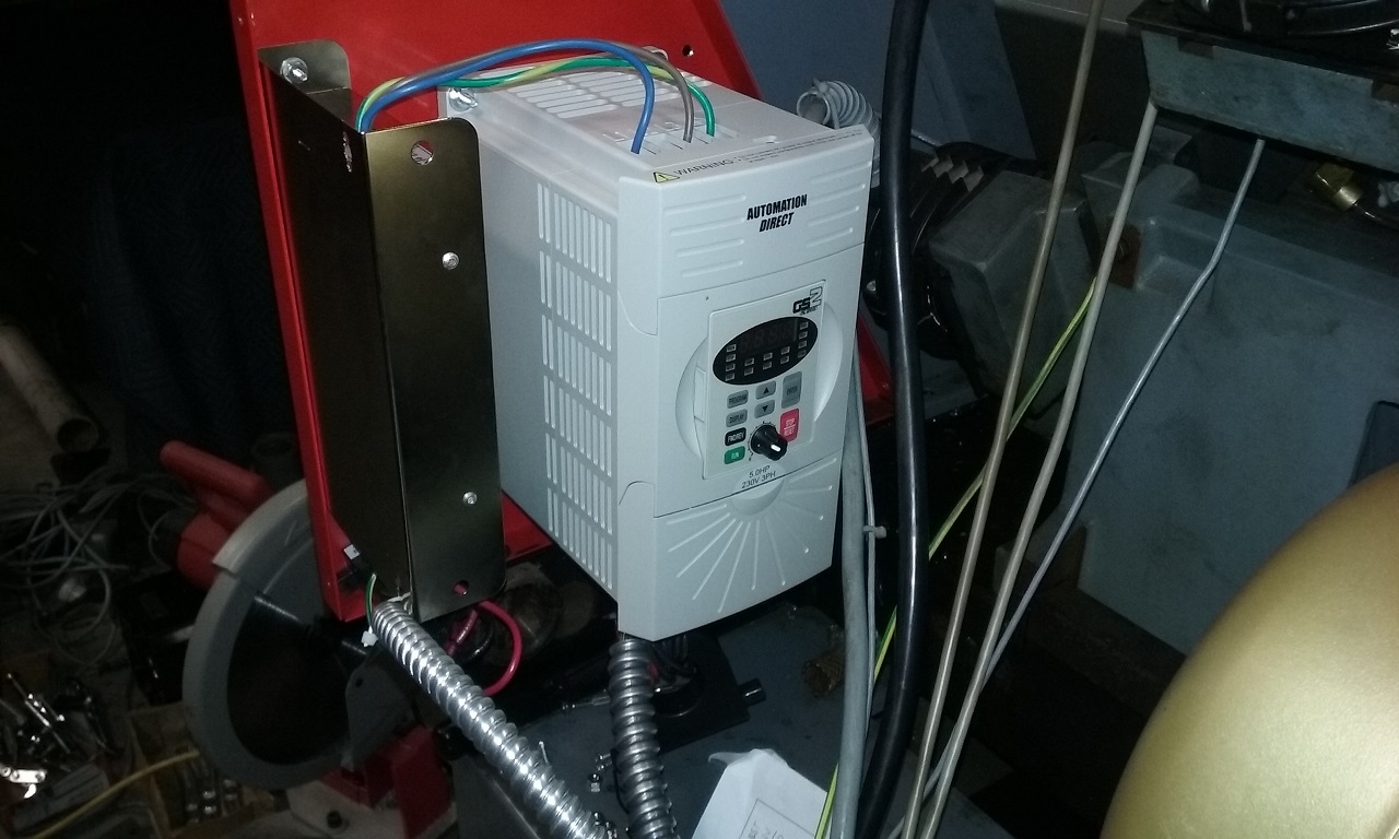
thanx, I guess it was a $75 lesson for me. I have the Automation Direct GS2 on site and will be installing it this weekend. Hopefully that will go easier than the other one.
Please Log in or Create an account to join the conversation.
- LutzTD
- Offline
- Elite Member
-
Less
More
- Posts: 216
- Thank you received: 1
07 Aug 2016 14:29 #78439
by LutzTD
Replied by LutzTD on topic Emcoturn 120 lathe retrofit
installed the Automation Direct GS2 drive. wired it up and ran it manually. seems to run OK on single phase. I'm wondering if I should go ahead and try to hook it up using modbus rather than 2 relays. I don't see any other way than relays for the 7i76e outputs as they do not switch the common on the VFD, they supply external voltage which is not allowed on the GS2. Problem is the 7i76e wants to use rs-422 and the VFD wants a rs-485 or rs-232 signal
.
.
Please Log in or Create an account to join the conversation.
- LutzTD
- Offline
- Elite Member
-
Less
More
- Posts: 216
- Thank you received: 1
07 Aug 2016 15:45 - 07 Aug 2016 15:46 #78443
by LutzTD
Replied by LutzTD on topic Emcoturn 120 lathe retrofit
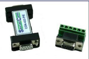
will this converter work? I see from the GS2 manual I cannot use the rs-232 5v to power any external device, this one has a 5v power input so I could run that from the 5v on the 7i76e card?
www.serialcomm.com/serial_rs232_converte...ct_general_info.aspx
www.serialcomm.com/serial_rs232_converte...ct_general_info.aspx
Last edit: 07 Aug 2016 15:46 by LutzTD.
Please Log in or Create an account to join the conversation.
- Todd Zuercher
-

- Offline
- Platinum Member
-

Less
More
- Posts: 4753
- Thank you received: 1458
07 Aug 2016 19:01 #78448
by Todd Zuercher
Replied by Todd Zuercher on topic Emcoturn 120 lathe retrofit
For modbus control of a VFD it is usually easiest to connect to the PC via a USB or RS232 adapter rather than through Mesa hardware. Unless you have the skills to write your own drivers for the mesa hardware to control your VFD. (I certainly don't)
Please Log in or Create an account to join the conversation.
Time to create page: 0.362 seconds