Downdraft design questions
- txtrone
-
 Topic Author
- Offline
- Platinum Member
-

Less
More
- Posts: 384
- Thank you received: 106
24 Dec 2020 14:25 #193112
by txtrone
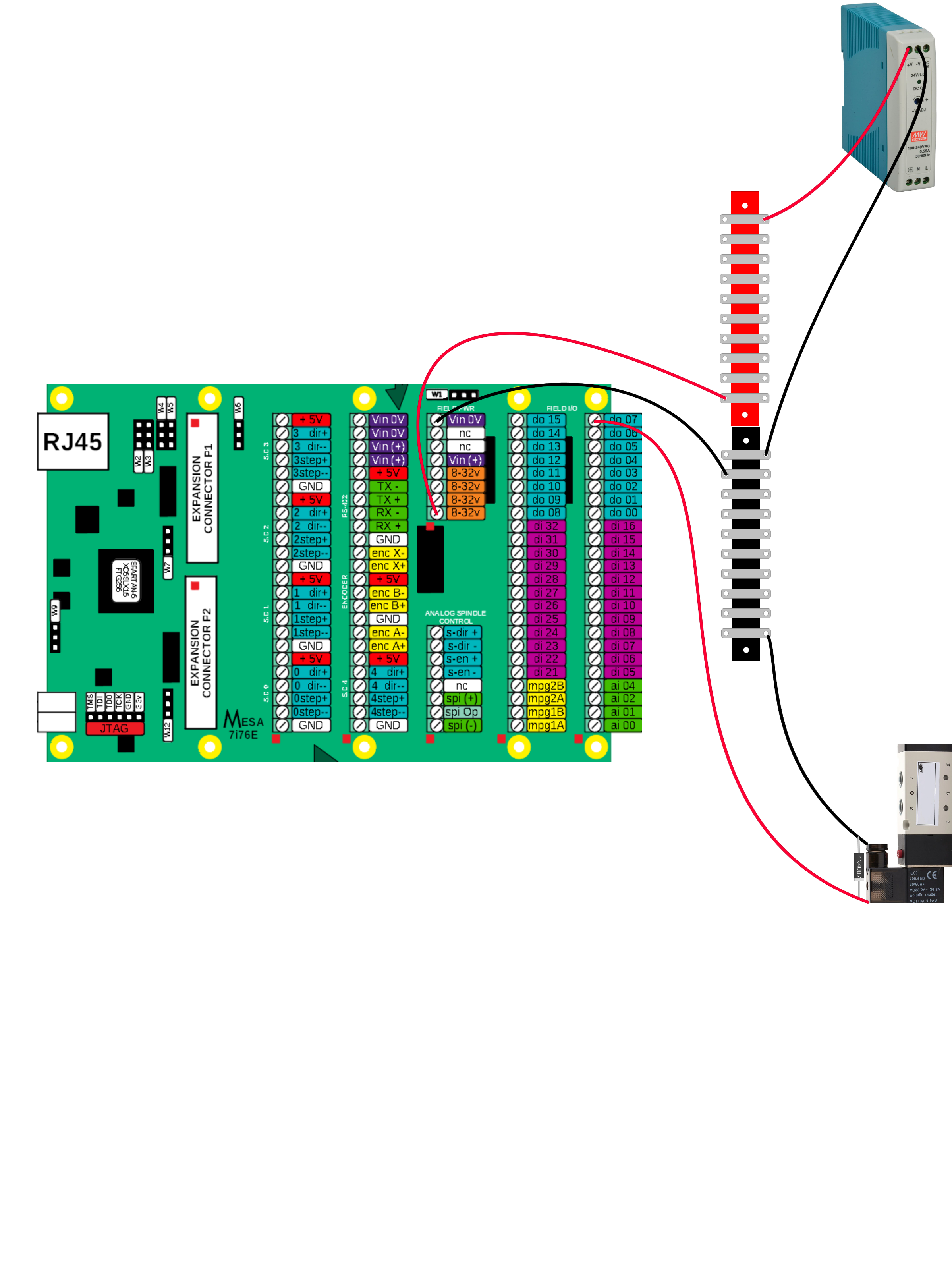
Like this? Or does the -24 need to go somewhere else?
Replied by txtrone on topic Downdraft design questions
VIN should not be used as it can be disconnected with the jumper, use the 8-32V pins on TB1 for powering the board.
Like this? Or does the -24 need to go somewhere else?
Attachments:
Please Log in or Create an account to join the conversation.
- Aciera
-

- Offline
- Administrator
-

Less
More
- Posts: 4717
- Thank you received: 2112
24 Dec 2020 15:05 - 24 Dec 2020 15:11 #193119
by Aciera
Replied by Aciera on topic Downdraft design questions
Ok, just for the record: There is no -24V here.
I get that you refer to the negative terminal of the 24V DC supply but lets call the positive terminal 24V and the negative terminal 0V or GND.
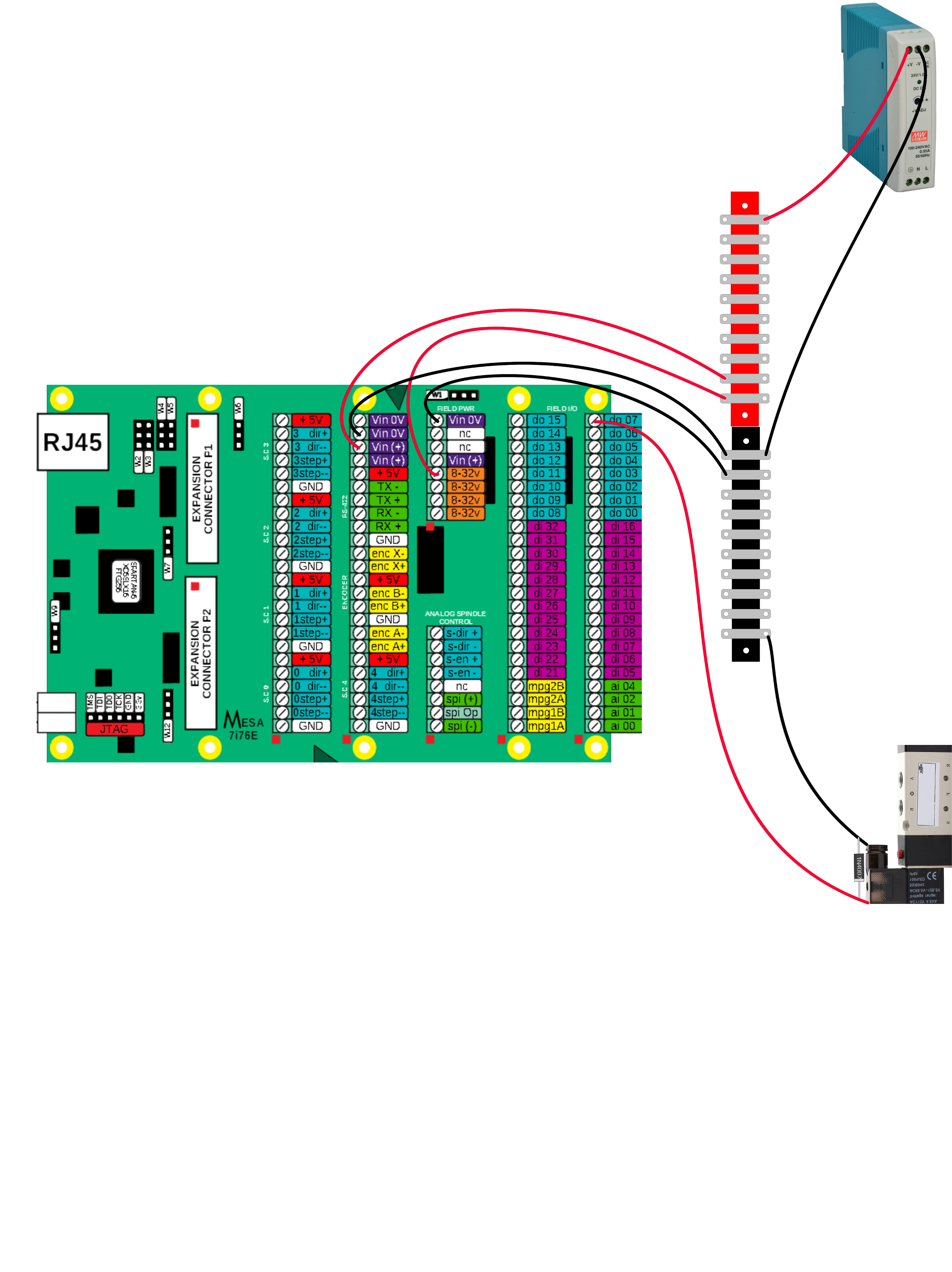
Now you're missing the power for the FPGA. So go back to the schematics before and just move the 24V from the "VIN" Pin to one of the "8-32V" Pins below that and bob's your uncle.
[edit]
In other words:
TB1 : Pin8 < GND, Pin4 < 24V
TB3 : Pin23 < GND, Pin22 < 24V
I get that you refer to the negative terminal of the 24V DC supply but lets call the positive terminal 24V and the negative terminal 0V or GND.
Now you're missing the power for the FPGA. So go back to the schematics before and just move the 24V from the "VIN" Pin to one of the "8-32V" Pins below that and bob's your uncle.
[edit]
In other words:
TB1 : Pin8 < GND, Pin4 < 24V
TB3 : Pin23 < GND, Pin22 < 24V
Last edit: 24 Dec 2020 15:11 by Aciera.
Please Log in or Create an account to join the conversation.
- txtrone
-
Topic Author
- Offline
- Platinum Member
-
Less
More
- Posts: 384
- Thank you received: 106
24 Dec 2020 15:22 #193123
by txtrone
So exactly like Norbert's schematic, except TB1 Pin5 should be Pin4 (or 3,2,1)?
How does this look?
Replied by txtrone on topic Downdraft design questions
Ok, just for the record: There is no -24V here.
I get that you refer to the negative terminal of the 24V DC supply but lets call the positive terminal 24V and the negative terminal 0V or GND.
Now you're missing the power for the FPGA. So go back to the schematics before and just move the 24V from the "VIN" Pin to one of the "8-32V" Pins below that and bob's your uncle.
[edit]
In other words:
TB1 : Pin8 < GND, Pin4 < 24V
TB3 : Pin23 < GND, Pin22 < 24V
So exactly like Norbert's schematic, except TB1 Pin5 should be Pin4 (or 3,2,1)?
How does this look?
Attachments:
Please Log in or Create an account to join the conversation.
- Aciera
-
- Offline
- Administrator
-
Less
More
- Posts: 4717
- Thank you received: 2112
24 Dec 2020 16:04 #193129
by Aciera
Replied by Aciera on topic Downdraft design questions
Yes, that looks good to me.
The following user(s) said Thank You: txtrone
Please Log in or Create an account to join the conversation.
- txtrone
-
Topic Author
- Offline
- Platinum Member
-
Less
More
- Posts: 384
- Thank you received: 106
24 Dec 2020 16:07 #193130
by txtrone
Replied by txtrone on topic Downdraft design questions
Thanks for holding my hand through that!
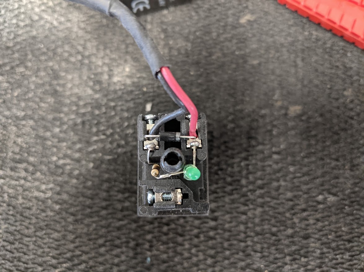
Do I have the diode polarity correct at the solenoid?
Do I have the diode polarity correct at the solenoid?
Please Log in or Create an account to join the conversation.
- Aciera
-
- Offline
- Administrator
-
Less
More
- Posts: 4717
- Thank you received: 2112
24 Dec 2020 16:15 #193132
by Aciera
Replied by Aciera on topic Downdraft design questions
Yes diode is fine like that.
The following user(s) said Thank You: txtrone
Please Log in or Create an account to join the conversation.
- txtrone
-
Topic Author
- Offline
- Platinum Member
-
Less
More
- Posts: 384
- Thank you received: 106
24 Dec 2020 16:19 #193133
by txtrone
Thanks again! Hopefully I can get the blast gates working over the holidays.
Replied by txtrone on topic Downdraft design questions
Yes diode is fine like that.
Thanks again! Hopefully I can get the blast gates working over the holidays.
The following user(s) said Thank You: rodw
Please Log in or Create an account to join the conversation.
- txtrone
-
Topic Author
- Offline
- Platinum Member
-
Less
More
- Posts: 384
- Thank you received: 106
25 Dec 2020 22:55 #193199
by txtrone
Replied by txtrone on topic Downdraft design questions
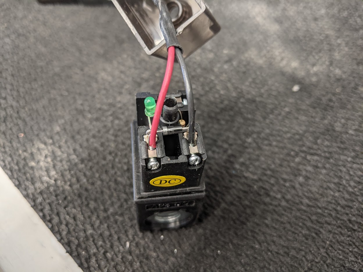
This is how I have the diodes wired across the solenoid terminals. Does this look correct? I did not connect the 'drain' wire to the solenoid, but I will connect it to a common bus, which will be connected to the cabinet ground.
Please Log in or Create an account to join the conversation.
- txtrone
-
Topic Author
- Offline
- Platinum Member
-
Less
More
- Posts: 384
- Thank you received: 106
26 Dec 2020 03:58 #193208
by txtrone
Replied by txtrone on topic Downdraft design questions
Sanity check before I go live.
This is the 7i76e, powered by 24v, attached to eight solenoids via digital outputs, with a diode across the terminals at each solenoid. I used two negative terminal blocks in the schematic to make this easier to look at. I am only using one in the cabinet.
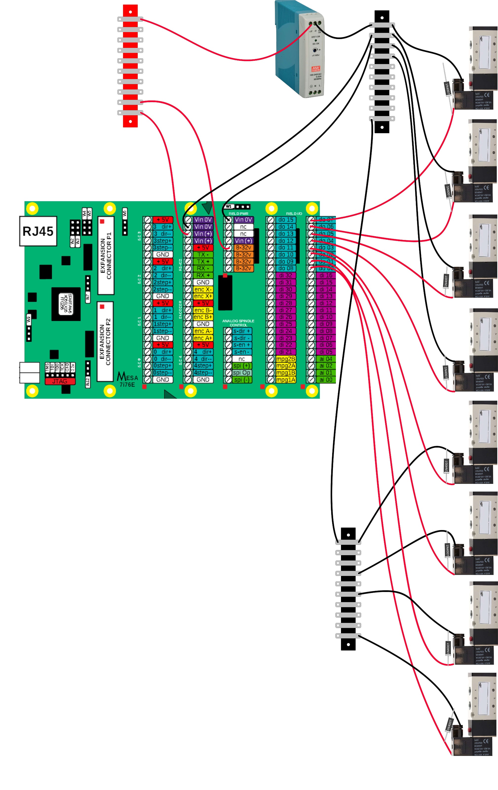
This is the 7i76e, powered by 24v, attached to eight solenoids via digital outputs, with a diode across the terminals at each solenoid. I used two negative terminal blocks in the schematic to make this easier to look at. I am only using one in the cabinet.
Please Log in or Create an account to join the conversation.
- rodw
-

- Offline
- Platinum Member
-
Less
More
- Posts: 11953
- Thank you received: 4069
26 Dec 2020 05:13 #193211
by rodw
Replied by rodw on topic Downdraft design questions
From what I can see, you should be good to go.
Wire in the power and check you have 5 volts on a stepgen (eg between TB2-1 and TB2-6)
I think I would get the motion side up and running if you have not already.
Then I would install the ddraft component and connect the outputs to them in hal.
Check with halshow its working like in the screen dump I shared.
Check with a multimeter that the pin goes high +24V (between the output pin and GND - TB1-8) in sync with Halshow.
So when you get that far you know all is good on the 7i76e side
So then power off the 7i76e and connect one solenoid to one output pin. Power up again and confirm that shutter fires in that segment.
Once happy, wire up the remaining solenoids and watch on with big grin while making music with jog wheel and air rams!
The following user(s) said Thank You: txtrone
Please Log in or Create an account to join the conversation.
Moderators: snowgoer540
Time to create page: 1.149 seconds