- Other Stuff
- Show Your Stuff
- 2+2+3 More Plasma builds, double the joy ! 3X2M and 2.5X1.5M cnc plasma build.
2+2+3 More Plasma builds, double the joy ! 3X2M and 2.5X1.5M cnc plasma build.
- tommylight
-
 Topic Author
- Away
- Moderator
-

- Posts: 21653
- Thank you received: 7397
I wonder who else has the same color machine on this forum...that blue paint looks familiar i can't put my finger on it
")
Please Log in or Create an account to join the conversation.
- Joco
-

- Offline
- Platinum Member
-

- Posts: 532
- Thank you received: 327
Cheers - J.
Please Log in or Create an account to join the conversation.
- tommylight
-
Topic Author
- Away
- Moderator
-
- Posts: 21653
- Thank you received: 7397
Most of the troubles with reductions are caused by the lack of that aluminium L profile, i have another 30CM of it left so i am saving as much as i can. Had found nearly 4 meters of it last year together with both of the profiles in pictures by accident and found out they were ordered by accident also, so i can not find it anymore, literally the guy had no idea he has that stuff in his shop till i sent him a picture of a small part that a friend of mine found in his yard, probably have to make an offer he cant refuse to push him to get me more!
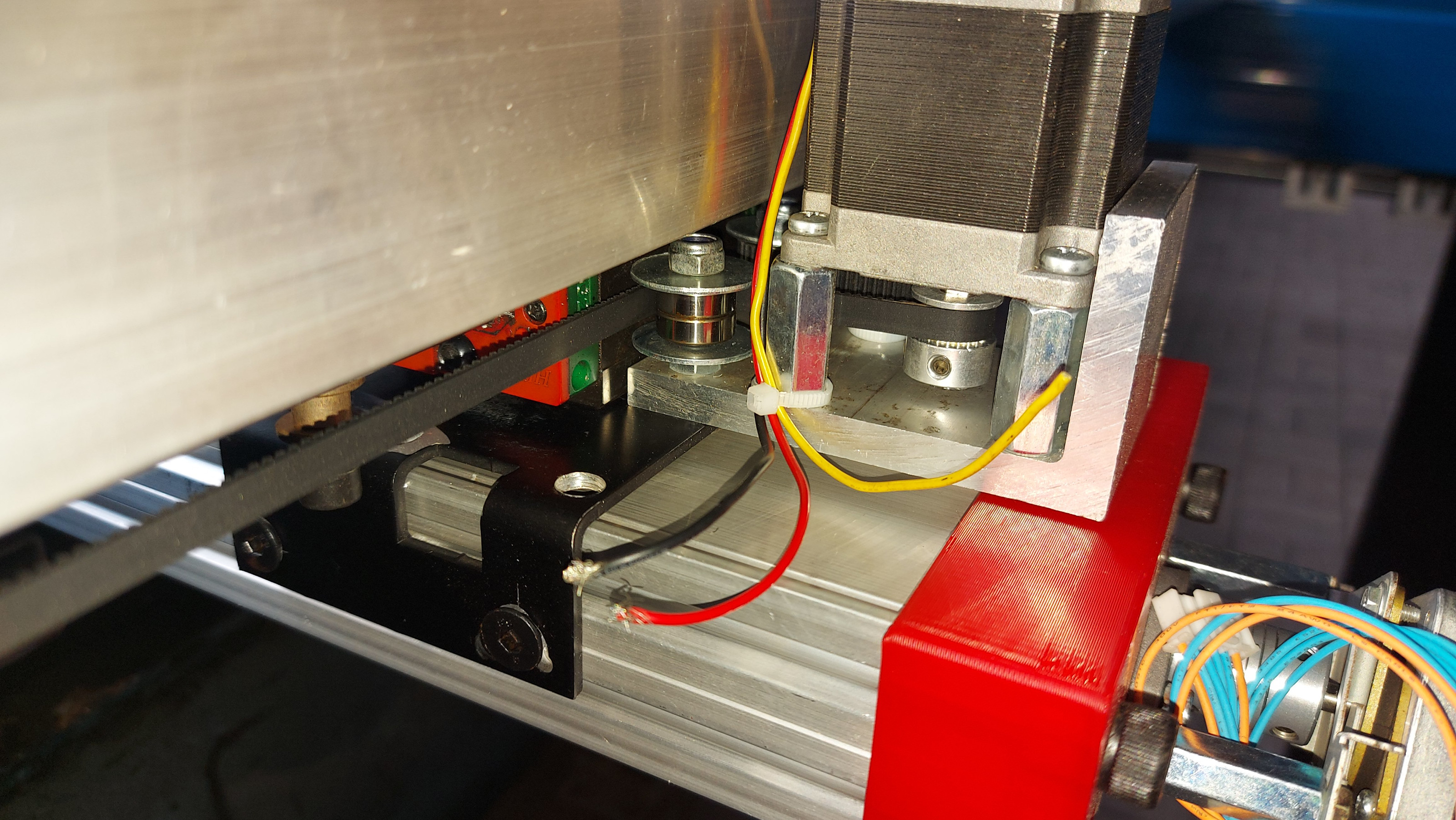
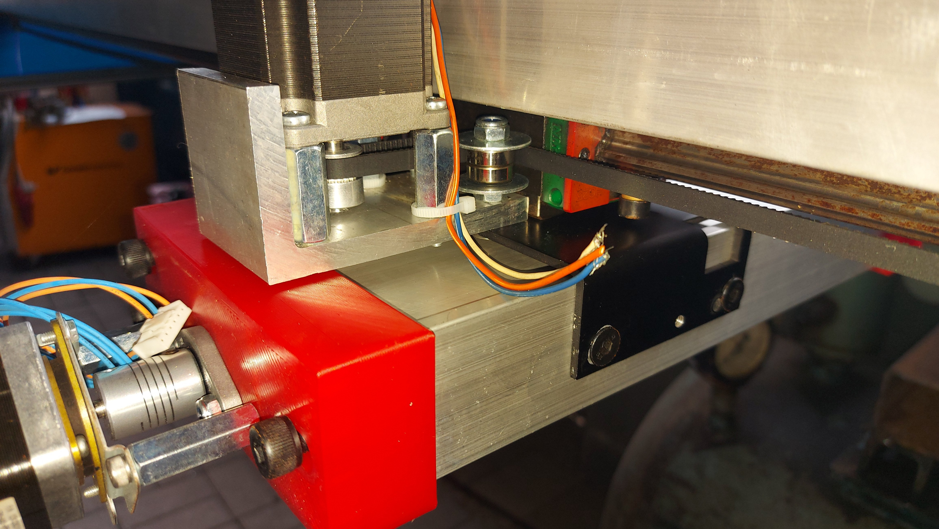
Attachments:
Please Log in or Create an account to join the conversation.
- Joco
-
- Offline
- Platinum Member
-
- Posts: 532
- Thank you received: 327
Please Log in or Create an account to join the conversation.
- tommylight
-
Topic Author
- Away
- Moderator
-
- Posts: 21653
- Thank you received: 7397
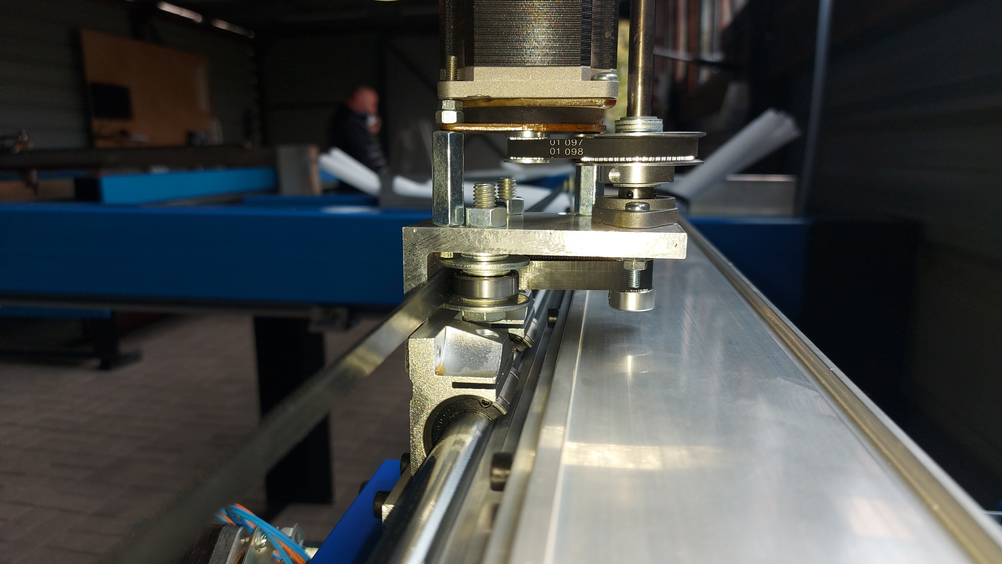
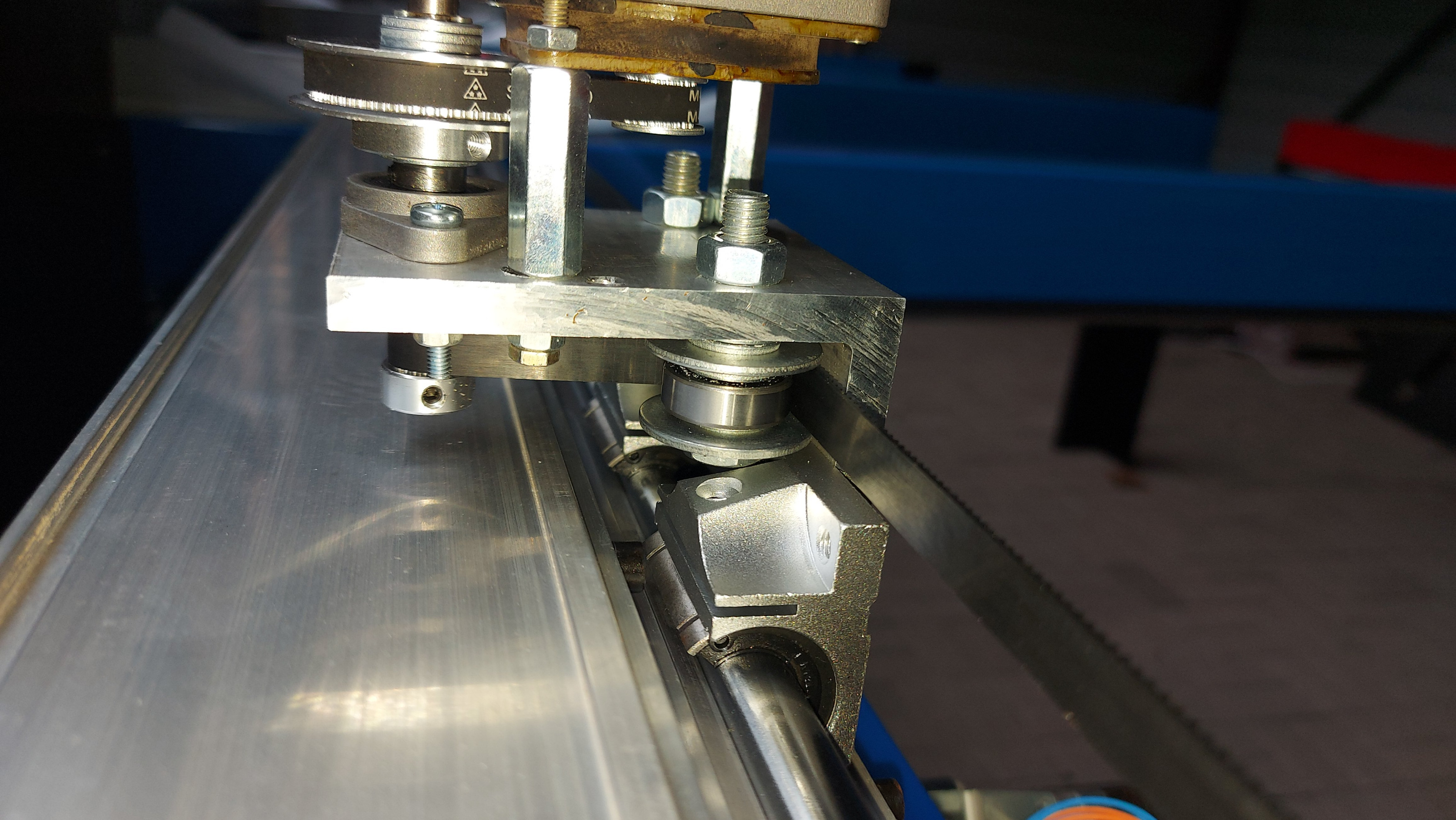
I also use 50X10 flat alu bar for the idlers on the Y axis, and this i can order again from Austria through a company i worked for, roughly 16 Euro/M, so i am happy with it.
Since we are here, by some dumb luck i did find M3x20 hex head screws, M3 heat inserts, and some days ago also found some cr@ppy M3x24 and M3x18! :) Spent over 3 months hunting those, talking about wasting perfectly good time...
Please Log in or Create an account to join the conversation.
- Joco
-
- Offline
- Platinum Member
-
- Posts: 532
- Thank you received: 327
What you using the M3's for? I'm mostly using, M4 (only for the linear rails), M5 and M6.
Please Log in or Create an account to join the conversation.
- Joco
-
- Offline
- Platinum Member
-
- Posts: 532
- Thank you received: 327
thanks - James.
Please Log in or Create an account to join the conversation.
- tommylight
-
Topic Author
- Away
- Moderator
-
- Posts: 21653
- Thank you received: 7397
6mm is more than enough for a reduction if the gantry does not weight in to much.
Squaring is easy since 2.8, no need to move switches or adjust screws or.... nothing really, all you need is a plate/plank/blanket/big piece of paper to mark the set points with a sharpie, at 0.0, 0.1000, 2000.1000, 2000.0, then measure diagonally between two of those points and other two of those points.
Be aware that when measuring if using a tape measure it is very important to have the tape always on the same side of the set points, messing that alone can skew about 1-2mm. Values above are example, use what your machine can handle. Also never edit both Y offset values in the .ini file at the same time.
Now, say the measured values came back 8mm longer on one side, that will roughly be 4mm out on one side so use that in the .ini for offset.
Please Log in or Create an account to join the conversation.
- Joco
-
- Offline
- Platinum Member
-
- Posts: 532
- Thank you received: 327
Ah 3D Printer - yup - gotcha. Yeah, I have a Hypercube Evolution I need to finish at some point.M3 are used in every 3D printer on the planet, while here are non existent.
I presume there homing swicthes can't be too far out of a square position else things are going to go wrong. So get them in place based on some ruler measurements ...6mm is more than enough for a reduction if the gantry does not weight in to much.
Squaring is easy since 2.8, no need to move switches or adjust screws or.... nothing really
then fine tune the home Y offset from where the switch triggers to get the a gantry that generates a rectangle/square shape that has equal diagonals. So you know it is square on all sides., all you need is a plate/plank/blanket/big piece of paper to mark the set points with a sharpie, at 0.0, 0.1000, 2000.1000, 2000.0, then measure diagonally between two of those points and other two of those points.
Be aware that when measuring if using a tape measure it is very important to have the tape always on the same side of the set points, messing that alone can skew about 1-2mm. Values above are example, use what your machine can handle. Also never edit both Y offset values in the .ini file at the same time.
Now, say the measured values came back 8mm longer on one side, that will roughly be 4mm out on one side so use that in the .ini for offset.
You could use a set square at your X check points. Have the setsquare so it reaches down to the paper/board/etc from the gantry after moving the Y to an asked for position.
When I get to that stage I will try and do a video of the process. Or write it all up with pics. Of course, it would help if my sensors would actually leave China.
Cheers - J.
Please Log in or Create an account to join the conversation.
- snowgoer540
-

- Offline
- Moderator
-
- Posts: 2552
- Thank you received: 884
Squaring is easy since 2.8, no need to move switches or adjust screws or....
I'm not sure how changing the offsets in the .ini file to affect squaring, instead of adjusting the sensors never occurred to me.
Brilliant!
Please Log in or Create an account to join the conversation.
- Other Stuff
- Show Your Stuff
- 2+2+3 More Plasma builds, double the joy ! 3X2M and 2.5X1.5M cnc plasma build.