1982 Matsuura MC-500v Retrofit
- chopper79
-
 Topic Author
- Offline
- Elite Member
-

Less
More
- Posts: 193
- Thank you received: 44
29 Jan 2017 06:32 #86883
by chopper79
Replied by chopper79 on topic 1982 Matsuura MC-500v Retrofit
@ skunkworks
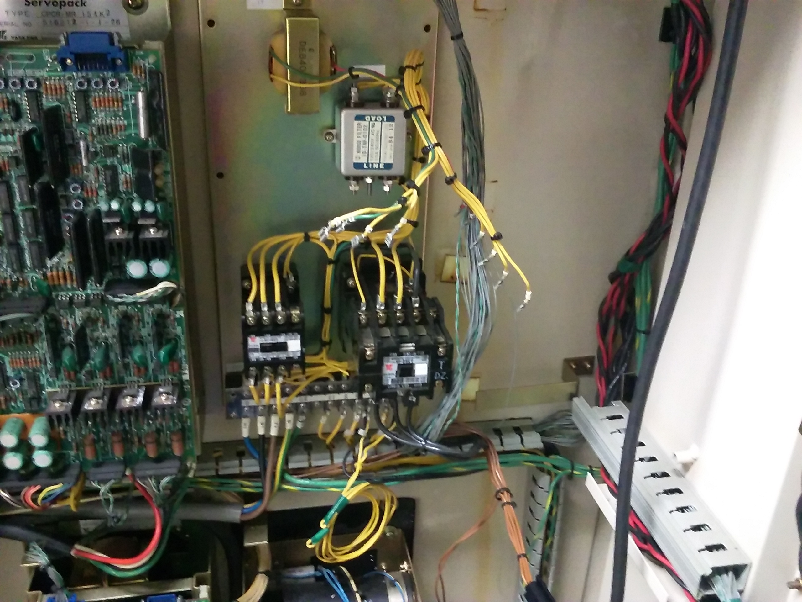
There are the two large 3 pole contacts in the drive side enclosure. I seen you removed the relay board that was over them. What did you do to make the contacts work again? I have been chasing this issue for a couple hours and I can not find any information on those contacts. My goal was to use the relay board. but again no information so I am resorting to removing the relay board.
There are the two large 3 pole contacts in the drive side enclosure. I seen you removed the relay board that was over them. What did you do to make the contacts work again? I have been chasing this issue for a couple hours and I can not find any information on those contacts. My goal was to use the relay board. but again no information so I am resorting to removing the relay board.
Please Log in or Create an account to join the conversation.
- chopper79
-
Topic Author
- Offline
- Elite Member
-
Less
More
- Posts: 193
- Thank you received: 44
29 Jan 2017 22:51 #86934
by chopper79
Replied by chopper79 on topic 1982 Matsuura MC-500v Retrofit
I managed to get the original relay board working so far. Took some searching with my multi-meter. Now those contacts work when triggered.
Working on the lcnc install now. I am following this build from this thread for lcnc on mint.
forum.linuxcnc.org/9-installing-linuxcnc...-or-deb?limitstart=0
I will update with results.
Working on the lcnc install now. I am following this build from this thread for lcnc on mint.
forum.linuxcnc.org/9-installing-linuxcnc...-or-deb?limitstart=0
I will update with results.
Please Log in or Create an account to join the conversation.
- chopper79
-
Topic Author
- Offline
- Elite Member
-
Less
More
- Posts: 193
- Thank you received: 44
05 Feb 2017 06:29 #87333
by chopper79
Replied by chopper79 on topic 1982 Matsuura MC-500v Retrofit
Making slow progress on the retrofit. Software setup blues at the moment.
Here is a couple pictures of the mess so far. Once I get the computer and hardware to play nice then I can start making this look better. Also WORK!!
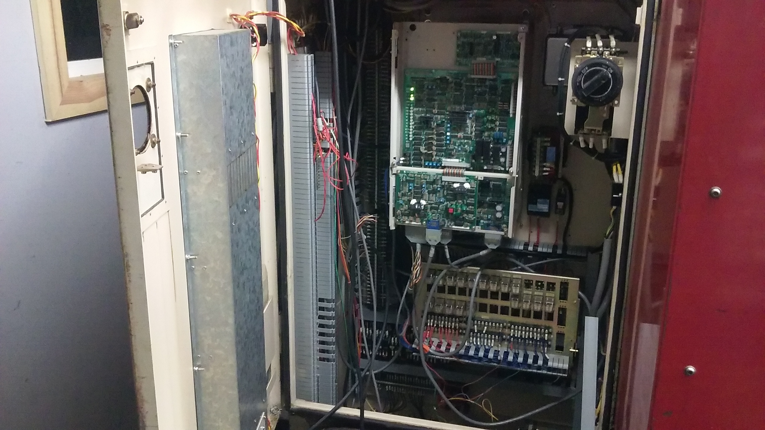
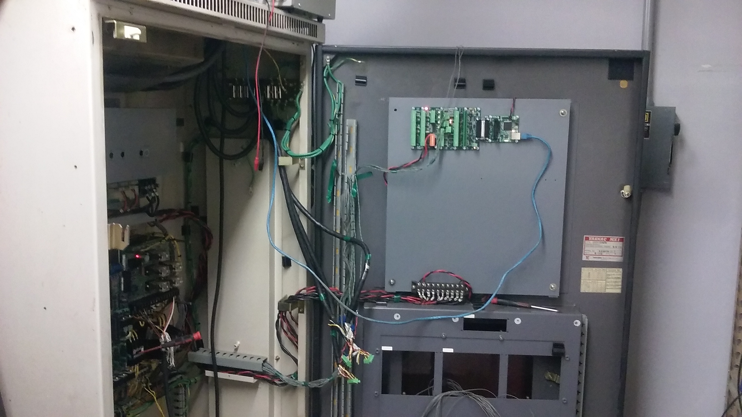
Here is a couple pictures of the mess so far. Once I get the computer and hardware to play nice then I can start making this look better. Also WORK!!
Please Log in or Create an account to join the conversation.
- chopper79
-
Topic Author
- Offline
- Elite Member
-
Less
More
- Posts: 193
- Thank you received: 44
08 Feb 2017 06:36 - 08 Feb 2017 06:42 #87513
by chopper79
Replied by chopper79 on topic 1982 Matsuura MC-500v Retrofit
After many dumb errors on my behalf, there is movement. Still need to put in correct encoder count, ballscrew information, Then I can move onto the spindle, the i/o for the tool changer and limits. Using a 7i92 + 7i77 for interface boards running via Ethernet. Feels good to see it moving....
Milestone #2 achieved!!! A big Thank you goes out to the fellow LCNC users/developers that helped me with a few issues I have been having.
Milestone #2 achieved!!! A big Thank you goes out to the fellow LCNC users/developers that helped me with a few issues I have been having.
Last edit: 08 Feb 2017 06:42 by chopper79.
Please Log in or Create an account to join the conversation.
- chopper79
-
Topic Author
- Offline
- Elite Member
-
Less
More
- Posts: 193
- Thank you received: 44
08 Feb 2017 15:46 - 08 Feb 2017 15:48 #87572
by chopper79
Replied by chopper79 on topic 1982 Matsuura MC-500v Retrofit
Ok... This is just to document the information I am finding on the factory encoders. Hope this helps somebody else in the future.
Encoders are Yaskawa TFUE Series
ie: tfue-(25)zd7 = 2500ppr encoder. (First 2 number * 100 = ppr)
There are two types of encoders offered, they are a 12v and a 5v style. You will need the 5v style and this is determined by the part number also. The following will determine the voltage.
tfue-25z(d)7 -> the D = 5v encoder
tfue-25z(c)7 -> the C = 12v encoder
My machine came with the 5v style encoders so there was no need to change them over.
Last edit: 08 Feb 2017 15:48 by chopper79.
Please Log in or Create an account to join the conversation.
- skunkworks
- Offline
- Moderator
-

Less
More
- Posts: 349
- Thank you received: 152
08 Feb 2017 15:52 #87574
by skunkworks
Replied by skunkworks on topic 1982 Matsuura MC-500v Retrofit
The inch input scale for ours was 25400 ")
The following user(s) said Thank You: chopper79
Please Log in or Create an account to join the conversation.
- chopper79
-
Topic Author
- Offline
- Elite Member
-
Less
More
- Posts: 193
- Thank you received: 44
08 Feb 2017 16:18 #87580
by chopper79
Replied by chopper79 on topic 1982 Matsuura MC-500v Retrofit
I have attached a link for all the manuals I have about the MC-500v2. Some of these manuals are specific to my machine, but most are general manuals. The file included wiring, operation, service, drive manuals, spindle manuals, etc. Good little collection of files for anybody who needs them. I will continue to add information to this link as I get it.
Hope this helps somebody in the future.
STUFF
* wanted to upload files here, bu they are greater than 1.6mb so I had to go back to my dropbox link.
Hope this helps somebody in the future.
STUFF
* wanted to upload files here, bu they are greater than 1.6mb so I had to go back to my dropbox link.
The following user(s) said Thank You: sinusvag
Please Log in or Create an account to join the conversation.
- chopper79
-
Topic Author
- Offline
- Elite Member
-
Less
More
- Posts: 193
- Thank you received: 44
08 Feb 2017 16:20 - 09 Feb 2017 00:29 #87581
by chopper79
Replied by chopper79 on topic 1982 Matsuura MC-500v Retrofit
Ball Screw information:
X axis = 12mm pitch
Y axis = 12mm pitch
Z axis = 10mm pitch
When used with the factory encoders and motors you will have the following (if you have same equipment)
X axis = TFUE30ZD7 encoder (3000ppr) with a 12mm pitch ball screw = 25399.9992 scale
Y axis = TFUE30ZD7 encoder (3000ppr) with a 12mm pitch ball screw = 25399.9992 scale
Z axis = TFUE25ZD7 encoder (2500ppr) with a 10mm pitch ball screw = 25399.9992 scale
Using factory settings on drives and my old FERROR values (.05) I am at 600ipm on both X &Y. The Z axis is at 475ipm. The acceleration is set at 30.0 on each axis.
FERROR will be reduced as PID tuning happens. I am sure the as I reduce the FERROR value I will also be reducing the IPM on each axis. I hope not but we will see.
Last edit: 09 Feb 2017 00:29 by chopper79.
Please Log in or Create an account to join the conversation.
- chopper79
-
Topic Author
- Offline
- Elite Member
-
Less
More
- Posts: 193
- Thank you received: 44
11 Feb 2017 17:38 - 11 Feb 2017 17:43 #87827
by chopper79
Replied by chopper79 on topic 1982 Matsuura MC-500v Retrofit
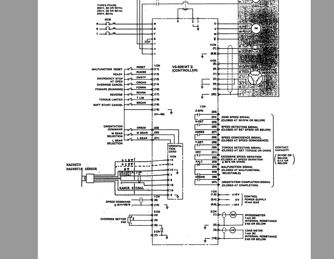
Working on getting my spindle running. I am hesitant to connect some of the signal wires. I know I need the following:
Inputs
Pin 9 = Speed command +/- 10v
Pin 10 = Signal ground
Pin 12 = Ready
Pin 15 = Signal ground
Pin 16 = FWD run
Pin 17 = REV run
Pin 22 = Spindle Orientation
My mind is not allowing me to come to a definite answer on if I should take 24vdc + to the pins to close the contact (excluding signal ground pins and speed control pins). Should I?
I normally do not have issues reading a schematic, but today I am. Also I am a little worried about burning up an expensive part like a VFD. Gun shy I guess.... Any help the connections would be wonderful.
Last edit: 11 Feb 2017 17:43 by chopper79.
Please Log in or Create an account to join the conversation.
- PCW
-

- Offline
- Moderator
-
Less
More
- Posts: 17925
- Thank you received: 5250
11 Feb 2017 17:47 #87829
by PCW
Replied by PCW on topic 1982 Matsuura MC-500v Retrofit
Looks like the pins are switched to ground to enable
24V applied to any of those pins is likely to damage the drive
24V applied to any of those pins is likely to damage the drive
The following user(s) said Thank You: chopper79
Please Log in or Create an account to join the conversation.
Time to create page: 2.392 seconds