1982 Matsuura MC-500v Retrofit
- chopper79
-
 Topic Author
- Offline
- Elite Member
-

Less
More
- Posts: 193
- Thank you received: 44
24 Feb 2017 13:55 - 24 Feb 2017 20:45 #88584
by chopper79
Replied by chopper79 on topic 1982 Matsuura MC-500v Retrofit
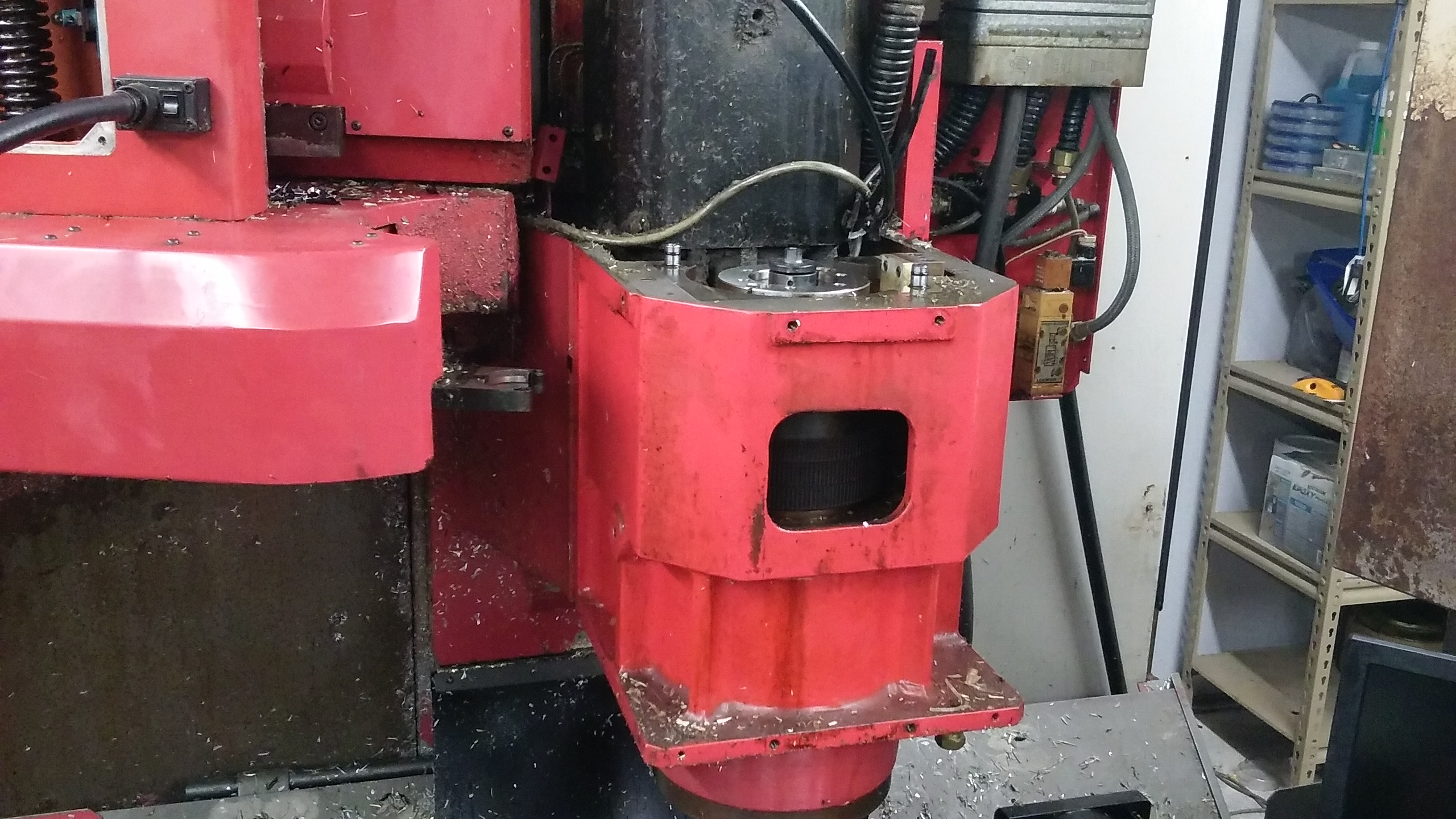
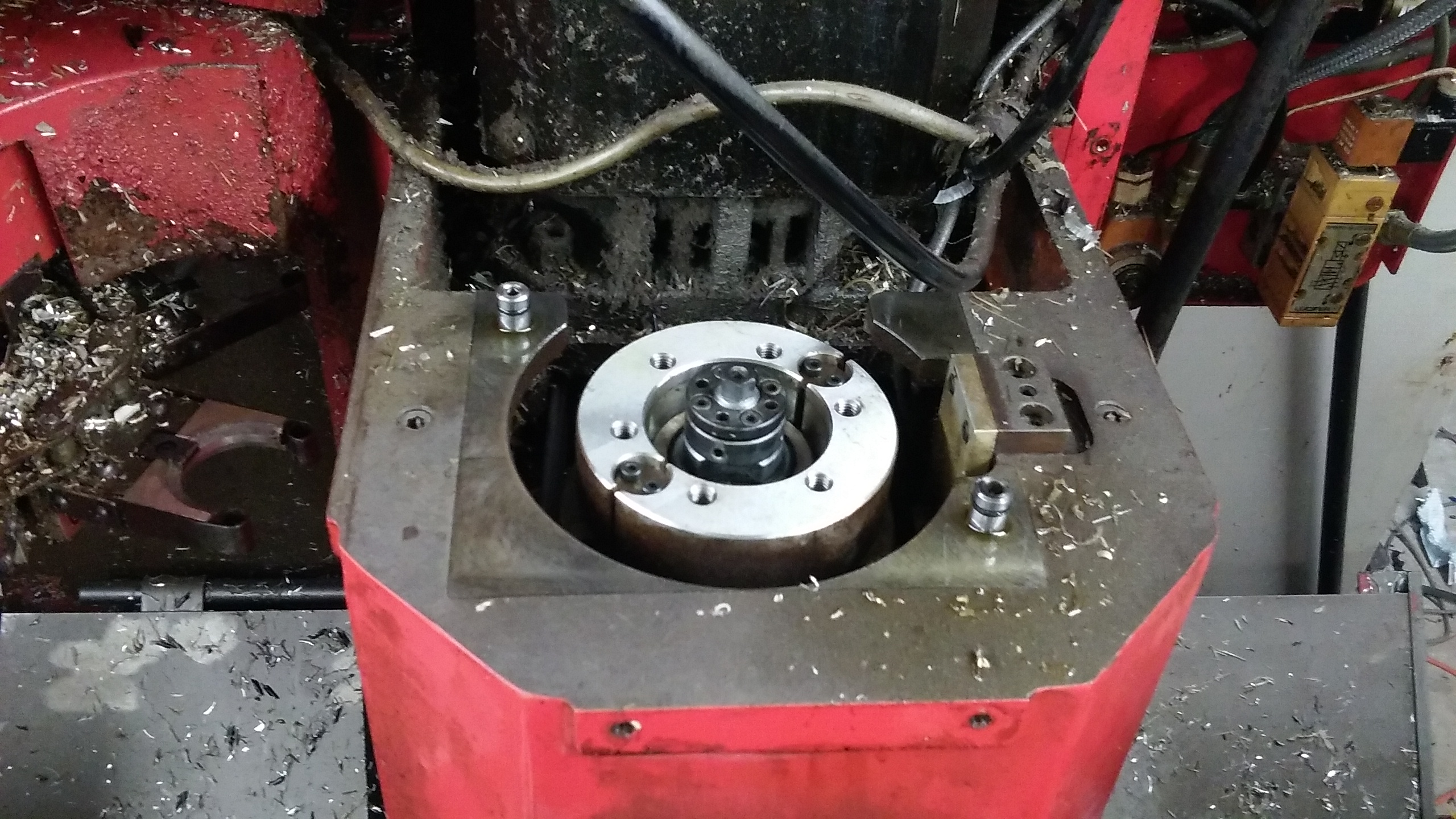
The gear for the encoder will go in this location. The silver collar will need to be removed and the gear will go below this and attach via bolts to the spindle cartridge. This part will have to go back into position so the tool unclamp and clap functions still work.
You will see on the right side of the opening a mounting bracket that is for the pickups for orientation of the spindle. It is held in by (2) socket cap screws. I am going to attempt to use that bracket for mounting my encoder pickups. This will make it more of a factory type install and keep it easy to service in the future.
Here are pictures of part that needs to come off to get the gear in. I am going to find me a gear today and will update with what I found. There will also need to be some machining done to this gear for things to mount and fit well.
Last edit: 24 Feb 2017 20:45 by chopper79.
Please Log in or Create an account to join the conversation.
- chopper79
-
Topic Author
- Offline
- Elite Member
-
Less
More
- Posts: 193
- Thank you received: 44
24 Feb 2017 18:41 - 24 Feb 2017 18:43 #88589
by chopper79
Replied by chopper79 on topic 1982 Matsuura MC-500v Retrofit
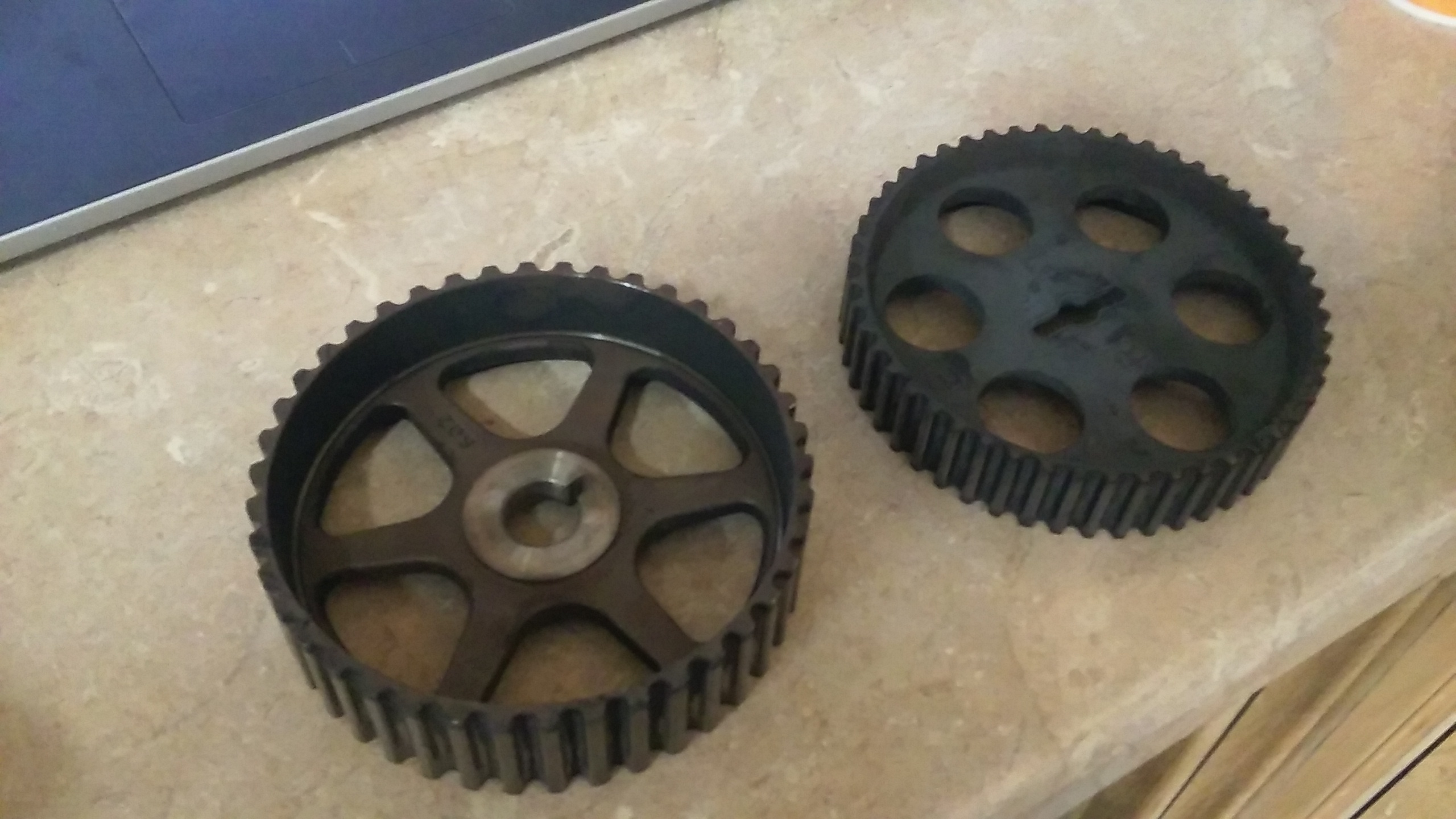
Found two pulleys to choose form. I would liked them to be about .375" larger in diameter. Now to machine the insides of them to flatten out the mounting surfaces. They may not even work well either.....
The deep dish one is a 42 tooth (left one) and the other is a 50 tooth (right one). The deep dish one would be the ideal one to use as the dish would give better sensor mounting options. I just worry about it being a 42 tooth gear and it being so low in tooth count. Andy stated earlier that he has used a 50 tooth one before then I suppose the 42 tooth one would work fine as well. I mean its better then what is one there which is a single hall for indexing.
Thoughts?
(I am still looking for a better gear also just in case)
Last edit: 24 Feb 2017 18:43 by chopper79.
Please Log in or Create an account to join the conversation.
- tommylight
-

- Offline
- Moderator
-

Less
More
- Posts: 21699
- Thank you received: 7416
24 Feb 2017 18:48 #88590
by tommylight
Replied by tommylight on topic 1982 Matsuura MC-500v Retrofit
Those look like car cam shaft pulleys, they do not look like they have the same number of teeth, if you plan on rigid tapping, they must be 1 to 1 ratio.
Try to find a dual cam shaft engine, they have 2 of the same.
Regards,
Tom
Try to find a dual cam shaft engine, they have 2 of the same.
Regards,
Tom
Please Log in or Create an account to join the conversation.
- chopper79
-
Topic Author
- Offline
- Elite Member
-
Less
More
- Posts: 193
- Thank you received: 44
24 Feb 2017 18:50 - 24 Feb 2017 19:08 #88591
by chopper79
Replied by chopper79 on topic 1982 Matsuura MC-500v Retrofit
Yes they are cam shaft pulleys and I am only using one of them. Not sure which one if either would work fine.
Edit: If one of these does not do what I want then I will machine my own pulley and add as many teeth and mounting options as a I can. I wish I could make it from aluminum as then I have a 72 tooth pulley blank that I could use. Since the tooth sensors are magnetic...well, you get the idea.
Edit: If one of these does not do what I want then I will machine my own pulley and add as many teeth and mounting options as a I can. I wish I could make it from aluminum as then I have a 72 tooth pulley blank that I could use. Since the tooth sensors are magnetic...well, you get the idea.
Last edit: 24 Feb 2017 19:08 by chopper79.
Please Log in or Create an account to join the conversation.
- andypugh
-

- Offline
- Moderator
-
Less
More
- Posts: 19875
- Thank you received: 4642
24 Feb 2017 19:36 #88592
by andypugh
Lathe-threading works OK with a single pulse per rev.
Rigid-tapping on a mill needs more teeth to know at what point the spindle has reversed.
So, with a 42 tooth wheel you have 168 pulses per rev.
Tapping a 1/4" x 20 thread you have a pitch error of 1 / (20 * 168) inches. That's .0003". That would probably be lost in the spindle bearing end-float.
Replied by andypugh on topic 1982 Matsuura MC-500v Retrofit
I suppose the 42 tooth one would work fine as well. I mean its better then what is one there which is a single hall for indexing.
Lathe-threading works OK with a single pulse per rev.
Rigid-tapping on a mill needs more teeth to know at what point the spindle has reversed.
So, with a 42 tooth wheel you have 168 pulses per rev.
Tapping a 1/4" x 20 thread you have a pitch error of 1 / (20 * 168) inches. That's .0003". That would probably be lost in the spindle bearing end-float.
Please Log in or Create an account to join the conversation.
- chopper79
-
Topic Author
- Offline
- Elite Member
-
Less
More
- Posts: 193
- Thank you received: 44
24 Feb 2017 19:43 - 24 Feb 2017 20:32 #88594
by chopper79
Replied by chopper79 on topic 1982 Matsuura MC-500v Retrofit
Hmm.... I use all metric threads. Might be an issue then if a 1/4-20 has that much error correct?
Thread sizes from M3 up to M6
May need to look into a higher count pulley to increase my ppr. Unless the 42 tooth would be fine when doing metric threads?
Thread sizes from M3 up to M6
May need to look into a higher count pulley to increase my ppr. Unless the 42 tooth would be fine when doing metric threads?
Last edit: 24 Feb 2017 20:32 by chopper79.
Please Log in or Create an account to join the conversation.
- chopper79
-
Topic Author
- Offline
- Elite Member
-
Less
More
- Posts: 193
- Thank you received: 44
24 Feb 2017 20:04 - 24 Feb 2017 20:04 #88595
by chopper79
Replied by chopper79 on topic 1982 Matsuura MC-500v Retrofit
Doing some thinking on this.....
The machine tapped using a g84 from the factory. This means there had to be some sort of feedback from the spindle to the controller. Started looking at the manual for the spindle motor and there is something in there but not sure if this would be able to be used?
Might have to hook a meter up to these and see..
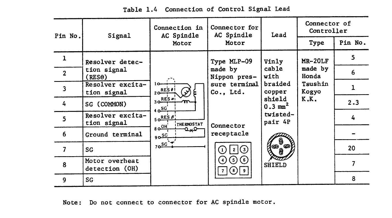
Last edit: 24 Feb 2017 20:04 by chopper79.
Please Log in or Create an account to join the conversation.
- andypugh
-
- Offline
- Moderator
-
Less
More
- Posts: 19875
- Thank you received: 4642
24 Feb 2017 20:59 #88597
by andypugh
Replied by andypugh on topic 1982 Matsuura MC-500v Retrofit
Oh, you have a resolver!
What feedback do the axis motors use? It seems odd to have a spindle resolver and axis encoders?
My machines use Resolvers on both axes and spindles (I like them) but I chose my Mesa cards based around the 7i49, which I don't think is a comfortable fit to your system.
You should be able to use the resolver to quadrature converter from Pico, though.
The following user(s) said Thank You: chopper79
Please Log in or Create an account to join the conversation.
- andypugh
-
- Offline
- Moderator
-
Less
More
- Posts: 19875
- Thank you received: 4642
24 Feb 2017 21:00 #88598
by andypugh
So do I, I was converting :_0
M6 x 1 would have 6 µm of pitch error on back-out with the 42 tooth wheel. Again, unlikely to be a problem.
Replied by andypugh on topic 1982 Matsuura MC-500v Retrofit
Hmm.... I use all metric threads.
So do I, I was converting :_0
M6 x 1 would have 6 µm of pitch error on back-out with the 42 tooth wheel. Again, unlikely to be a problem.
The following user(s) said Thank You: chopper79
Please Log in or Create an account to join the conversation.
- chopper79
-
Topic Author
- Offline
- Elite Member
-
Less
More
- Posts: 193
- Thank you received: 44
24 Feb 2017 21:48 - 24 Feb 2017 21:58 #88600
by chopper79
X, Y, and Z all have encoders. The spindle has the resolver.
That is good to know. I may just go ahead and use one of the gears I have and give it a go. I was going to order 3 of these to do the counting and index. The pico card you linked to is out of my price range. I can afford the ~ $24.00 in sensors though.
Sensors
Replied by chopper79 on topic 1982 Matsuura MC-500v Retrofit
Oh, you have a resolver!
What feedback do the axis motors use? It seems odd to have a spindle resolver and axis encoders?
X, Y, and Z all have encoders. The spindle has the resolver.
So do I, I was converting :_0
M6 x 1 would have 6 µm of pitch error on back-out with the 42 tooth wheel. Again, unlikely to be a problem.
That is good to know. I may just go ahead and use one of the gears I have and give it a go. I was going to order 3 of these to do the counting and index. The pico card you linked to is out of my price range. I can afford the ~ $24.00 in sensors though.
Sensors
Last edit: 24 Feb 2017 21:58 by chopper79.
Please Log in or Create an account to join the conversation.
Time to create page: 0.308 seconds