Build: XZero Predator... With more teeth!
- ihavenofish
- Away
- Platinum Member
-

Less
More
- Posts: 1025
- Thank you received: 286
04 Jun 2019 21:08 #135860
by ihavenofish
Build: XZero Predator... With more teeth! was created by ihavenofish
So, with my 2 brother tapping centres in storage, no 3 phase power, and no messy/noisy space to play, I have decided to have some fun with my XZero predator.
In its last incarnation before disassembly and storage, it looked like this:
control specs were:
- linuxcnc 2.5 ?
- mesa 7i76 / 5i25
- leadshine 8NM nema34 closed loop steppers
- dual 2525 ballscrews in the x
- 2525 ballscrew in the y
- 2510 ballscrew in the Z
- top safe speed of 984ipm in x and y
There were a number of issues with this machine the way it was set up.
1: dual x drive ball screws is more trouble than it's worth. Sounded like a great idea, but more than one the gantry was forced to twist when the motors didn't behave.
2: The teknomotor atc spindle on their is FAR too heavy for this machine at over 50lbs.
3: I never liked the leadshine steppers a whole lot. They never tracked as well as i wanted them to at higher speeds, hence the restriction to only 984ipm. I guess they showed me just how bad steppers track at high speed under load - you just never get to see it on a readout")
We are going to see if we can correct all the issues, and make this machine vastly better than it used to be.
Part 1 is altering the machines frame. This is almost done. I replaced all the extruded parts on the machine (lower frame beams and gantry lower cross beam) with solid aluminium. Some say this is overkill. I disagree. Its just the right amount of kill
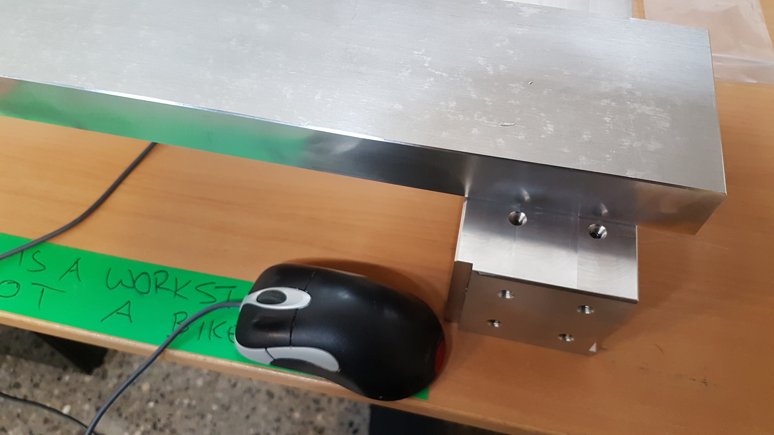
In the process, I reduced the machine length from about 41" travel to 16" travel. This is both to make the machine a whole lot stiffer and to make it FIT where i need to put it. 16" travel is perfect for guitars and most of the other things i need to make.
I am waiting on a newly made Z axis now. The original Z axis was fine, but overhung the machine quite a lot. I also happened to have a few extra linear guide blocks, so the new Y and Z will both have 4 long 25mm blocks. There wants really any problems with the original design of 2 long blocks per axis, but.. if your gonna remake it anyway.. why not? I will as a result lose travel on the Y and Z, but i will still be left with 29" x 7.5" (x 16" for the x) which is ample. My last change is the table. I am putting 4 1x2" cross bars across the frame, 100mm apart. A 750mm x 350mm 1/2" think aluminium vacuum plate will mount on top of these. Sacrificial mdf sheets, or a vise can also be mounted on top of these bars as different needs arise. A large laser cut aluminium sheet will cover the whole frame between the cross bars to keep debris out of the bottom of the machine and off the ball screw. I'll be anodising the whole machine black once all the aluminium parts are made.
Up next:
DRIVING THIS BEAST!
In its last incarnation before disassembly and storage, it looked like this:
control specs were:
- linuxcnc 2.5 ?
- mesa 7i76 / 5i25
- leadshine 8NM nema34 closed loop steppers
- dual 2525 ballscrews in the x
- 2525 ballscrew in the y
- 2510 ballscrew in the Z
- top safe speed of 984ipm in x and y
There were a number of issues with this machine the way it was set up.
1: dual x drive ball screws is more trouble than it's worth. Sounded like a great idea, but more than one the gantry was forced to twist when the motors didn't behave.
2: The teknomotor atc spindle on their is FAR too heavy for this machine at over 50lbs.
3: I never liked the leadshine steppers a whole lot. They never tracked as well as i wanted them to at higher speeds, hence the restriction to only 984ipm. I guess they showed me just how bad steppers track at high speed under load - you just never get to see it on a readout
We are going to see if we can correct all the issues, and make this machine vastly better than it used to be.
Part 1 is altering the machines frame. This is almost done. I replaced all the extruded parts on the machine (lower frame beams and gantry lower cross beam) with solid aluminium. Some say this is overkill. I disagree. Its just the right amount of kill
In the process, I reduced the machine length from about 41" travel to 16" travel. This is both to make the machine a whole lot stiffer and to make it FIT where i need to put it. 16" travel is perfect for guitars and most of the other things i need to make.
I am waiting on a newly made Z axis now. The original Z axis was fine, but overhung the machine quite a lot. I also happened to have a few extra linear guide blocks, so the new Y and Z will both have 4 long 25mm blocks. There wants really any problems with the original design of 2 long blocks per axis, but.. if your gonna remake it anyway.. why not? I will as a result lose travel on the Y and Z, but i will still be left with 29" x 7.5" (x 16" for the x) which is ample. My last change is the table. I am putting 4 1x2" cross bars across the frame, 100mm apart. A 750mm x 350mm 1/2" think aluminium vacuum plate will mount on top of these. Sacrificial mdf sheets, or a vise can also be mounted on top of these bars as different needs arise. A large laser cut aluminium sheet will cover the whole frame between the cross bars to keep debris out of the bottom of the machine and off the ball screw. I'll be anodising the whole machine black once all the aluminium parts are made.
Up next:
DRIVING THIS BEAST!
Attachments:
Please Log in or Create an account to join the conversation.
- tommylight
-

- Offline
- Moderator
-

Less
More
- Posts: 21722
- Thank you received: 7423
04 Jun 2019 23:24 #135875
by tommylight
Replied by tommylight on topic Build: XZero Predator... With more teeth!
That is a nice overkill !
Please Log in or Create an account to join the conversation.
- ihavenofish
- Away
- Platinum Member
-
Less
More
- Posts: 1025
- Thank you received: 286
05 Jun 2019 04:08 #135902
by ihavenofish
Replied by ihavenofish on topic Build: XZero Predator... With more teeth!
Stage 2....
Well, as mentioned, I didn't really like the leadshine closed loop steppers. They are good on a 5 or 10 pitch srcew, but 25mm pitch at high speed, doesn't work well.
So, what do I replace them with?
I have in my possession one solution - a set of 3 sanyo denki R series 30 amp (400w-750w) drives with analogue and pulse input. They are rated for 220v 3 phase though. I need 220v single phase. No ones buying them in a big rush on ebay, and they are very high performance compared to lower cost kits you can buy new (these run the new brother speedios), so, would be nice to make use of them.
Can we make them run single phase? What happens?
www.robosan.com.tr/pdfs/SANYO%20DENKİ%20...0DRIVER%20MANUAL.pdf
RS1L03AT
Manual says on page 3-7 you can wire it with single phase 220.. or even 110. in fact, I have the control side wired to 100v single right now on my desk and am poking at parameters....
Based on the motor charts you will get reduced peak current capacity on 220v single, and I assume reduced speed and peak current with single 110v? I don't think 110v is really recommended unless you have a correct 100v motor.
So, that seems plausible. But we have no motor. I bought these to run the sanyo motors in my brother, but those motors are too old and sanyo doesn't - well, REFUSES - to make a motor profile to run them. So I need to get myself 3 motors that are on the approved list.
That list allows P series, Q series, and new R series motors from 400W to 1KW.
There are plenty of P5 500W 86mm (not nema34) motors all over ebay for about $200 a pop shipped. these have 1.6nm continuous torque, 2nm at stall, and 6nm peak, and are only 15A peak (our amp is 30 on 3 phase), so they should be able to push this machine around easily. Drawback is they are WELL used and usually ship from china which means it will take ages and may be sketchy if one is bad.
www.melco.com.hk/data/P5.pdf
P50B08050
HMMM.
Anyone got a Sanyo P5 they want to send me for testing?
Please Log in or Create an account to join the conversation.
- ihavenofish
- Away
- Platinum Member
-
Less
More
- Posts: 1025
- Thank you received: 286
05 Jun 2019 04:09 - 05 Jun 2019 13:34 #135903
by ihavenofish
Replied by ihavenofish on topic Build: XZero Predator... With more teeth!
Well, after some searching, seems many of these Chinese sellers have the same pictures of the same motor... and feedback suggesting they are not entirely reputable. Hmmmm. Not wanting to risk that.
Last edit: 05 Jun 2019 13:34 by ihavenofish.
Please Log in or Create an account to join the conversation.
- ihavenofish
- Away
- Platinum Member
-
Less
More
- Posts: 1025
- Thank you received: 286
05 Jun 2019 17:59 #135965
by ihavenofish
Replied by ihavenofish on topic Build: XZero Predator... With more teeth!
The journey continues.
I have a spreadsheet i made years ago that tells me how much torque i need to move a machine given screw pitch, acceleration, cutting loads. it also tells me distances to accelerate - which is important cause going 5000ipm in 8" travel... probably not going to happen
What this tells me is that for my Y axis, i can spin up to 2000ipm on my 25 pitch screw and cut with 60lbs of tangential force (about the max my new spindle can dish out) and accelerate at 0.5G with a mere 400w. Well, a 400W sanyo motor. There is a distinction, being developed for massive overload use in tapping centers, where a lot of other servos only expect overload used in emergency situations. Sanyo gives you a usage chart! You can use 125% torque for several minutes and 200% for 10 second for example with their 76mm frame 400w motor. That motor also has more torque at lower speeds - 1.4NM. With most acceleration moves being in the sub 1 second time range followed by a larger break and our drive is quite oversized, using the "peak" torque is totally viable.
As a result of looking for this new smaller motor, i found a non sketchy seller of that motor for a good price on ebay, so I may get that one first for my testing. if it all fails, no big loss.
Math also says this same 400w servo with a brake is adequate for me Z, which uses a 10 pitch screw, and only has a 12 or so KG to move around. I found a seller for that motor too.
My X (gantry is heavy. Very heavy. HaHa. Math is telling me though that the sanyo 750w motor will do nicely. There are many of these available, they cost more because these are brother TC-S2A XY motors, but, i am willing to spend the money when i know the other motors and drives run.
So, maybe, just maybe, we have a motor solution here.
We will have a machine with 2000ipm in the y and x axes, with 0.5G acceleration.
The Z would be a comfortable 787ipm with 0.5G acceleration as well. This is twice the speed of the machine as it is running in the video. ZOOM.
We cant go any faster than this unfortunately. The screw are preloaded rolled ones, and they get HOT at high speed. i ran all 3 at 2700ipm in testing. 2000rpm is safe.
Just for kicks, here is 1.5g and 800ipm. Yup, its getting up to speed in that distance.
I do now have one question about linuxcnc relating to these motors. Can linuxCNC specify a different acceleration for rapid moves and feed moves? 2000ipm is only for rapids. Cutting is unlikely to ever happen above 600ipm. If we could reduce the cutting acceleration to 0.3G for example, and bump the rapid acceleration up to 0.6G, we could get the ideal use of these motors without having to compromise with an acceleration that can be handled during a heavy cut.
In the next episode:
A CUSTOM CONTROL PANEL!!!!
The following user(s) said Thank You: chimeno, tommylight
Please Log in or Create an account to join the conversation.
- ihavenofish
- Away
- Platinum Member
-
Less
More
- Posts: 1025
- Thank you received: 286
05 Jun 2019 23:03 #135982
by ihavenofish
Replied by ihavenofish on topic Build: XZero Predator... With more teeth!
Alrighty...
That Y axis motor we will have in the next month.
In the meantime, I need to plan out a control panel. I've had this in the works for years, but i should be able to make it properly now if i can get some pointers on interfacing it.
We start with this: www.adafruit.com/product/1716
And then add in this: www.adafruit.com/product/1751
My lenovo has displayport, so the apple retina display is kinda perfect. I already have this kit. I bought it 3-4 years ago. It will behave just like any normal 2K monitor on a PC. Resolution is of course overkill, but.. that's the theme of this build isn't it?
I will have in my possession shortly a large format 3D printer (anycubic chiron). I will use it to print the housing for this panel then sand it smooth and nice and paint it. I may add in some reinforcement for durability - a fiberglass veil layer or 2 i think.
Before we get that far though, we need ourselves some buttons to push.
These are pretty: www.adafruit.com/product/3954 maybe 4 or 6 of those.
Tie them to this: www.adafruit.com/product/2000 and load some HID firmware.
Now we have a keyboard with programmable RGB lighting on each button.
The keypad will be framed into the panel bezel, and over each button we will 3D print a clear (ish) hard plastic cover. Paint those covers black and then laser away the paint to reveal icons, letters, etc, that the LEDs can shine through.
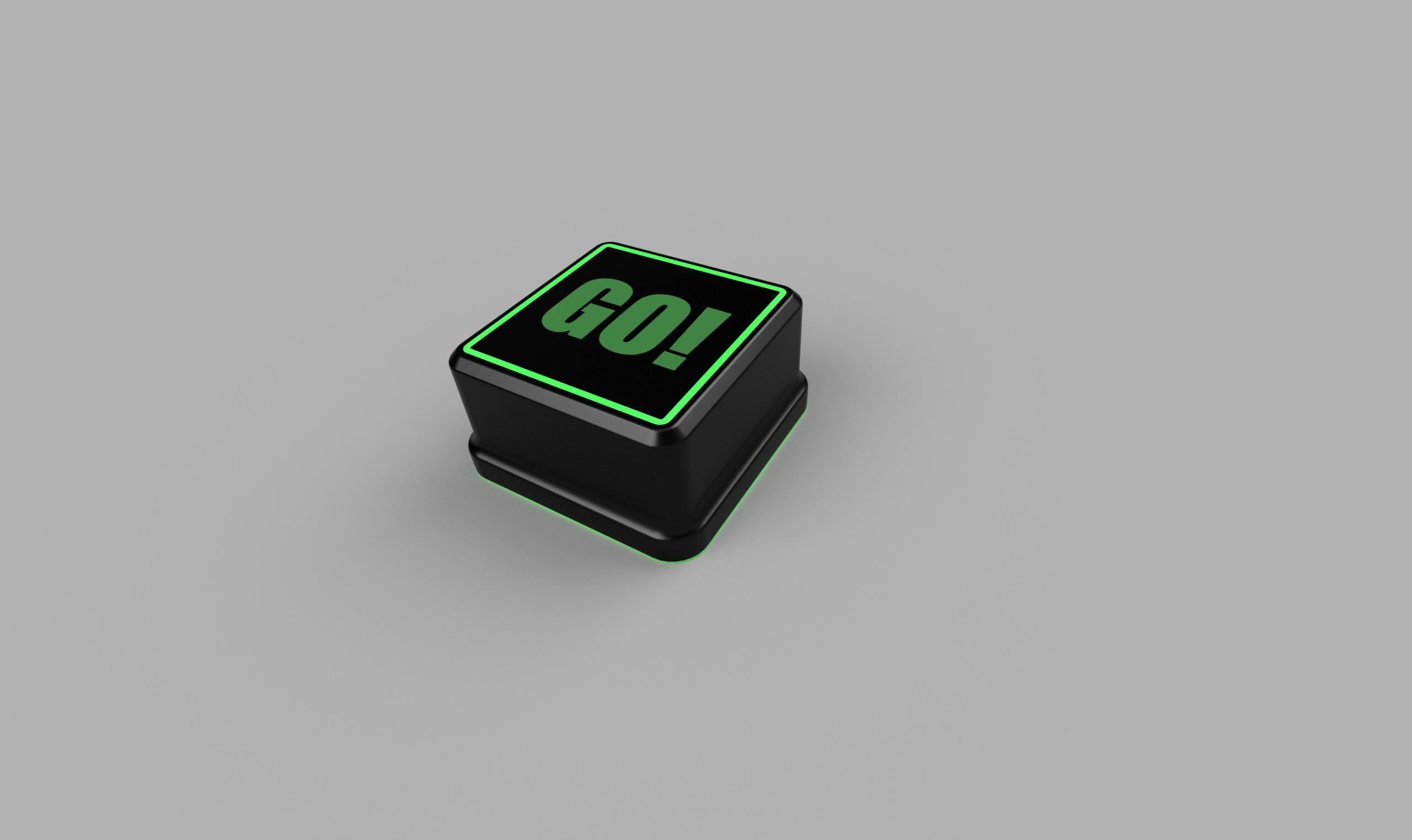
Down on the bottom we need a few more things. an E stop button, a machine power on and off button, maybe a separate flashy start and pause button set. Oh, and an LED bar, this one to display spindle motor load. green up to 100% then shifting to red when overloaded.
Last, but not lease, i need a couple encoders, with 3D printed dials and rings of LEDs. The will be for feed override and spindle override.
I lied, that wasn't last. We also need an MPG encoder dial. I can steal that out of a cheap MPG i have in a box.
So, Now we have a few more linuxcnc questions
What is the best way to deal with our buttons and LEDs?
The keys themselves could easily just bee a HID keyboard. Even the dials could emulate keyboard functions easily. But to have the lighting work, I expect this might be more complex. Ha anyone done an advanced keyboard panel? Is they a standard way to do it in linuxcnc to have full functionality here?
Thanks
That Y axis motor we will have in the next month.
In the meantime, I need to plan out a control panel. I've had this in the works for years, but i should be able to make it properly now if i can get some pointers on interfacing it.
We start with this: www.adafruit.com/product/1716
And then add in this: www.adafruit.com/product/1751
My lenovo has displayport, so the apple retina display is kinda perfect. I already have this kit. I bought it 3-4 years ago. It will behave just like any normal 2K monitor on a PC. Resolution is of course overkill, but.. that's the theme of this build isn't it?
I will have in my possession shortly a large format 3D printer (anycubic chiron). I will use it to print the housing for this panel then sand it smooth and nice and paint it. I may add in some reinforcement for durability - a fiberglass veil layer or 2 i think.
Before we get that far though, we need ourselves some buttons to push.
These are pretty: www.adafruit.com/product/3954 maybe 4 or 6 of those.
Tie them to this: www.adafruit.com/product/2000 and load some HID firmware.
Now we have a keyboard with programmable RGB lighting on each button.
The keypad will be framed into the panel bezel, and over each button we will 3D print a clear (ish) hard plastic cover. Paint those covers black and then laser away the paint to reveal icons, letters, etc, that the LEDs can shine through.
Down on the bottom we need a few more things. an E stop button, a machine power on and off button, maybe a separate flashy start and pause button set. Oh, and an LED bar, this one to display spindle motor load. green up to 100% then shifting to red when overloaded.
Last, but not lease, i need a couple encoders, with 3D printed dials and rings of LEDs. The will be for feed override and spindle override.
I lied, that wasn't last. We also need an MPG encoder dial. I can steal that out of a cheap MPG i have in a box.
So, Now we have a few more linuxcnc questions
What is the best way to deal with our buttons and LEDs?
The keys themselves could easily just bee a HID keyboard. Even the dials could emulate keyboard functions easily. But to have the lighting work, I expect this might be more complex. Ha anyone done an advanced keyboard panel? Is they a standard way to do it in linuxcnc to have full functionality here?
Thanks
Please Log in or Create an account to join the conversation.
- tommylight
-
- Offline
- Moderator
-
Less
More
- Posts: 21722
- Thank you received: 7423
05 Jun 2019 23:50 #135987
by tommylight
Replied by tommylight on topic Build: XZero Predator... With more teeth!
Nice!
For the panel you can use the Mesa 7i73 as it is made exactly for that purpose, it supports LCD screens and even some OLED ones lately, matrix keyboards, and plenty of I/O pins. The best thing is it is completely wired and powered through a network cable with RJ45 connectors. It does require having a Mesa card with an serial port or connector, many of them do have it.
For the panel you can use the Mesa 7i73 as it is made exactly for that purpose, it supports LCD screens and even some OLED ones lately, matrix keyboards, and plenty of I/O pins. The best thing is it is completely wired and powered through a network cable with RJ45 connectors. It does require having a Mesa card with an serial port or connector, many of them do have it.
Please Log in or Create an account to join the conversation.
- ihavenofish
- Away
- Platinum Member
-
Less
More
- Posts: 1025
- Thank you received: 286
06 Jun 2019 00:34 - 06 Jun 2019 00:36 #135993
by ihavenofish
Replied by ihavenofish on topic Build: XZero Predator... With more teeth!
I'm not sure that's applicable. The key panels and their LEDs are I2C controlled via the Arduino board, which has a usb interface.
The display is displayport, so its "just a monitor".
The display is displayport, so its "just a monitor".
Last edit: 06 Jun 2019 00:36 by ihavenofish.
Please Log in or Create an account to join the conversation.
- ihavenofish
- Away
- Platinum Member
-
Less
More
- Posts: 1025
- Thank you received: 286
06 Jun 2019 22:45 #136119
by ihavenofish
Replied by ihavenofish on topic Build: XZero Predator... With more teeth!
A button
Will be 3D printed from something translucent and strong. Nylon if i can make paint stick to it. Airbrushed black. Laser etched border for lighting to shine through. Water slide decal for the text, and then clear coated for some durability.
Repeat 96 times.
These socket right over the silicone adafruit buttons. the little rim prevents them from falling off - and from breaking easily. The adafruit buttons have a very nice tactile feel to them. I've already got them on my desk of course... It would be nice if they were spaced a little wider, but they aren't so cramped that pressing the wrong button is an issue. Keeps the panel nice and small as well.
Ill upload some key layout drawings shortly. I am debating on how many key pads to have, I don't think we need the full qwerty key set. If we need that, we can always plug in a real keyboard.
Will be 3D printed from something translucent and strong. Nylon if i can make paint stick to it. Airbrushed black. Laser etched border for lighting to shine through. Water slide decal for the text, and then clear coated for some durability.
Repeat 96 times.
These socket right over the silicone adafruit buttons. the little rim prevents them from falling off - and from breaking easily. The adafruit buttons have a very nice tactile feel to them. I've already got them on my desk of course...
It would be nice if they were spaced a little wider, but they aren't so cramped that pressing the wrong button is an issue. Keeps the panel nice and small as well.Ill upload some key layout drawings shortly. I am debating on how many key pads to have, I don't think we need the full qwerty key set. If we need that, we can always plug in a real keyboard.
Attachments:
Please Log in or Create an account to join the conversation.
- tommylight
-
- Offline
- Moderator
-
Less
More
- Posts: 21722
- Thank you received: 7423
06 Jun 2019 23:27 #136128
by tommylight
Replied by tommylight on topic Build: XZero Predator... With more teeth!
Awesome !
Please Log in or Create an account to join the conversation.
Time to create page: 0.334 seconds