My Newb Plasma Table Attempted Build
- tommylight
-

- Offline
- Moderator
-

Less
More
- Posts: 21715
- Thank you received: 7420
11 Jun 2020 17:39 #171155
by tommylight
Replied by tommylight on topic My Newb Plasma Table Attempted Build
Cr@p, does that mean i have to do all the drawings for you ? ")
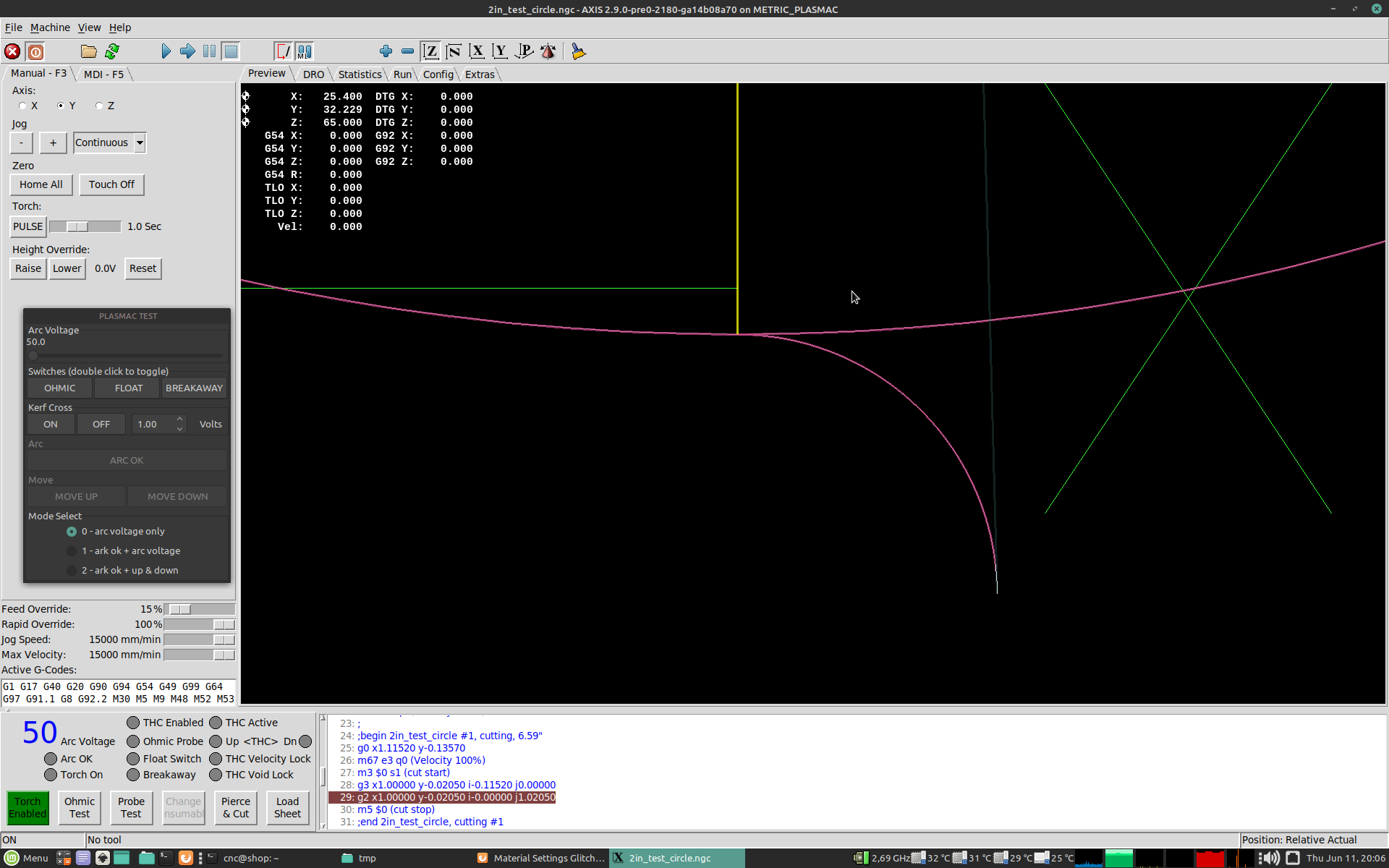
Post the gcode for that circle, lets have a look at what is there that can cause that.
Post the gcode for that circle, lets have a look at what is there that can cause that.
The following user(s) said Thank You: dvn4life1972
Please Log in or Create an account to join the conversation.
- dvn4life1972
- Offline
- Platinum Member
-

Less
More
- Posts: 401
- Thank you received: 173
11 Jun 2020 17:46 #171156
by dvn4life1972
Haha that was pretty funny! I think that until we can figure this all out and resolve the underlying issue, I may be able to use my dxf files in inkscape and generate the gcode to cut them from inside it. I don't have a bunch of parts that need to be nested at the moment, at least nothing that has a customer waiting for it.
Sheetcam 2" circle file attached. BTW, I did cut another square using the wizard without the lead-in/out and that made no difference...same issue.
Replied by dvn4life1972 on topic My Newb Plasma Table Attempted Build
Cr@p, does that mean i have to do all the drawings for you ?
Post the gcode for that circle, lets have a look at what is there that can cause that.
Haha that was pretty funny! I think that until we can figure this all out and resolve the underlying issue, I may be able to use my dxf files in inkscape and generate the gcode to cut them from inside it. I don't have a bunch of parts that need to be nested at the moment, at least nothing that has a customer waiting for it.
Sheetcam 2" circle file attached. BTW, I did cut another square using the wizard without the lead-in/out and that made no difference...same issue.
Please Log in or Create an account to join the conversation.
- Mike_Eitel
-

- Offline
- Platinum Member
-
Less
More
- Posts: 1052
- Thank you received: 183
11 Jun 2020 17:59 #171160
by Mike_Eitel
Replied by Mike_Eitel on topic My Newb Plasma Table Attempted Build
Sorry to long time:
What kind of motors? Anything "intelligent" with a deadband?
Any kind of backslash compensation?
This locks like there is somehow added a small offset to the first move. By either lcnc or by a contoller that had stopped with a deadband before.
Strange
What kind of motors? Anything "intelligent" with a deadband?
Any kind of backslash compensation?
This locks like there is somehow added a small offset to the first move. By either lcnc or by a contoller that had stopped with a deadband before.
Strange
The following user(s) said Thank You: dvn4life1972
Please Log in or Create an account to join the conversation.
- tommylight
-
- Offline
- Moderator
-
Less
More
- Posts: 21715
- Thank you received: 7420
11 Jun 2020 18:09 #171162
by tommylight
Replied by tommylight on topic My Newb Plasma Table Attempted Build
Your gcode, no issues.
You can remove the
M52 P1
line and test again, and remove the lead in and test without it.
One of those will do the trick, hopefully.
You can remove the
M52 P1
line and test again, and remove the lead in and test without it.
One of those will do the trick, hopefully.
Attachments:
The following user(s) said Thank You: dvn4life1972
Please Log in or Create an account to join the conversation.
- dvn4life1972
- Offline
- Platinum Member
-
Less
More
- Posts: 401
- Thank you received: 173
11 Jun 2020 18:58 #171165
by dvn4life1972
I'm absolutely new to all of this, so I'm not completely understanding what you mean by deadband. I agree that there is something programmed in the software that is not quite right and being triggered by one of the preamble M codes (like an offset of some kind). That's just my beginner's observation.
Replied by dvn4life1972 on topic My Newb Plasma Table Attempted Build
Sorry to long time:
What kind of motors? Anything "intelligent" with a deadband?
Any kind of backslash compensation?
This locks like there is somehow added a small offset to the first move. By either lcnc or by a contoller that had stopped with a deadband before.
Strange
I'm absolutely new to all of this, so I'm not completely understanding what you mean by deadband. I agree that there is something programmed in the software that is not quite right and being triggered by one of the preamble M codes (like an offset of some kind). That's just my beginner's observation.
Please Log in or Create an account to join the conversation.
- dvn4life1972
- Offline
- Platinum Member
-
Less
More
- Posts: 401
- Thank you received: 173
11 Jun 2020 18:59 #171166
by dvn4life1972
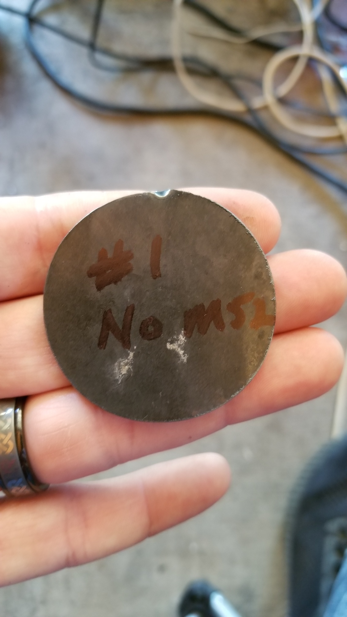
Tried #1 in pic with M52 P1 removed. Then removed lead-in and had the same result.
Replied by dvn4life1972 on topic My Newb Plasma Table Attempted Build
Your gcode, no issues.
You can remove the
M52 P1
line and test again, and remove the lead in and test without it.
One of those will do the trick, hopefully.
Tried #1 in pic with M52 P1 removed. Then removed lead-in and had the same result.
Please Log in or Create an account to join the conversation.
- Mike_Eitel
-
- Offline
- Platinum Member
-
Less
More
- Posts: 1052
- Thank you received: 183
11 Jun 2020 19:15 #171167
by Mike_Eitel
Replied by Mike_Eitel on topic My Newb Plasma Table Attempted Build
I'm not plasma. When i loock on your "punch" into the metal i had a silly idea.
If i understand correct you start by switching on air. In my eyes this must give some force on z axis witch will bend and move the torch. Probably 90 degrees away from the beam.
Maybe you can test something like that by just switching air on.
Mike
If i understand correct you start by switching on air. In my eyes this must give some force on z axis witch will bend and move the torch. Probably 90 degrees away from the beam.
Maybe you can test something like that by just switching air on.
Mike
The following user(s) said Thank You: dvn4life1972
Please Log in or Create an account to join the conversation.
- rodw
-

- Offline
- Platinum Member
-
Less
More
- Posts: 12007
- Thank you received: 4089
11 Jun 2020 19:23 - 11 Jun 2020 19:23 #171169
by rodw
Replied by rodw on topic My Newb Plasma Table Attempted Build
Its not really surprising that using adaptive feed and slowing down travel on holes (or circles) results in different dimensions., By slowing the feedrate down, the kerf will become wider (as there is more time to burn material away)
Also even without M52, on short segments, the planned velocity is likely constrained so your commanded feedrate is never achieved so you end up with a triangular acceleration profile.
What is the feedrate and what is your max acceleration setting?
So what you should do from here is to use halscope and plot motion.current.vel and compare the commanded velocity against the actual feedrate.
Please remember that plasma is a blunt axe, not a precision machining instrument.
Last edit: 11 Jun 2020 19:23 by rodw.
The following user(s) said Thank You: dvn4life1972
Please Log in or Create an account to join the conversation.
- dvn4life1972
- Offline
- Platinum Member
-
Less
More
- Posts: 401
- Thank you received: 173
11 Jun 2020 19:34 #171170
by dvn4life1972
Yes, I do know about how plasma is in the real world. Although I have never had or built a plasma table before, I did have a fabrication company where we outsourced to a vendor all of our parts cut work. Some we sourced for flame cutting, some plasma, some hi-def plasma, and some laser.
All that said, the bottom line is this: the machine was absolutely not doing this before, and abruptly began doing this afterward. When I try to cut a part out it actually begins to 'stack' the errors up (the more direction changes, the more off the mark it progressively gets). I just chose to use these simple shapes for diagnostic purposes, I had not been cutting them prior to the issue arising.
The problem is not the inherent properties and tendencies of the plasma process, it is something in the software. Removal of all of the M codes from the preamble have shown the error disappears, all other things being equal (same dimension piece to be cut, same air and amperage settings, same THC, etc). At this point honestly if I didn't have the time invested in the THCAD-10 for torch height, I would be buying a different controller strictly so I can get these orders out of my queue and then take my time working this issue. But, there is no other option that I am aware of with that card. To that end, it appears working the code via Inkscape will get those pending paying jobs taken care of. But that won't help when I need to nest parts and things such as that later.
I really wish I understood the software and gcode much better, but it's just gonna take time. Thanks for the help anyway Rod...
Replied by dvn4life1972 on topic My Newb Plasma Table Attempted Build
Its not really surprising that using adaptive feed and slowing down travel on holes (or circles) results in different dimensions., By slowing the feedrate down, the kerf will become wider (as there is more time to burn material away)
Also even without M52, on short segments, the planned velocity is likely constrained so your commanded feedrate is never achieved so you end up with a triangular acceleration profile.
What is the feedrate and what is your max acceleration setting?
So what you should do from here is to use halscope and plot motion.current.vel and compare the commanded velocity against the actual feedrate.
Please remember that plasma is a blunt axe, not a precision machining instrument.
Yes, I do know about how plasma is in the real world. Although I have never had or built a plasma table before, I did have a fabrication company where we outsourced to a vendor all of our parts cut work. Some we sourced for flame cutting, some plasma, some hi-def plasma, and some laser.
All that said, the bottom line is this: the machine was absolutely not doing this before, and abruptly began doing this afterward. When I try to cut a part out it actually begins to 'stack' the errors up (the more direction changes, the more off the mark it progressively gets). I just chose to use these simple shapes for diagnostic purposes, I had not been cutting them prior to the issue arising.
The problem is not the inherent properties and tendencies of the plasma process, it is something in the software. Removal of all of the M codes from the preamble have shown the error disappears, all other things being equal (same dimension piece to be cut, same air and amperage settings, same THC, etc). At this point honestly if I didn't have the time invested in the THCAD-10 for torch height, I would be buying a different controller strictly so I can get these orders out of my queue and then take my time working this issue. But, there is no other option that I am aware of with that card. To that end, it appears working the code via Inkscape will get those pending paying jobs taken care of. But that won't help when I need to nest parts and things such as that later.
I really wish I understood the software and gcode much better, but it's just gonna take time. Thanks for the help anyway Rod...
Please Log in or Create an account to join the conversation.
- dvn4life1972
- Offline
- Platinum Member
-
Less
More
- Posts: 401
- Thank you received: 173
11 Jun 2020 19:39 #171172
by dvn4life1972
The torch holder is very solidly attached to the Z axis. There is no play, I can actually lift up on the torch while it's attached and shift the table. It had some slop in it before which I took care of.
Replied by dvn4life1972 on topic My Newb Plasma Table Attempted Build
I'm not plasma. When i loock on your "punch" into the metal i had a silly idea.
If i understand correct you start by switching on air. In my eyes this must give some force on z axis witch will bend and move the torch. Probably 90 degrees away from the beam.
Maybe you can test something like that by just switching air on.
Mike
The torch holder is very solidly attached to the Z axis. There is no play, I can actually lift up on the torch while it's attached and shift the table. It had some slop in it before which I took care of.
Please Log in or Create an account to join the conversation.
Moderators: snowgoer540
Time to create page: 1.441 seconds