- Hardware & Machines
- CNC Machines
- Milling Machines
- Replacing Advanced Motion Controls "brush type 12A8 with "Axcent" amplifier
Replacing Advanced Motion Controls "brush type 12A8 with "Axcent" amplifier
- new2linux
- Offline
- Platinum Member
-

Less
More
- Posts: 711
- Thank you received: 9
19 Nov 2020 13:16 #189779
by new2linux
Replied by new2linux on topic Replacing Advanced Motion Controls "brush type 12A8 with "Axcent" amplifier
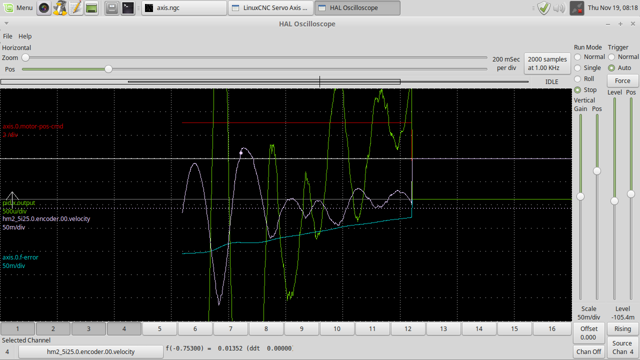
Todd, Thanks for your continued support!! I used the velocity as the source as per your suggestion. This is a pic of most recent tuning settings: Feed22"/min; P .111; D .05; FF1 .001; FF2 .0001; DEADBAND .00001
Many thanks
Many thanks
Attachments:
Please Log in or Create an account to join the conversation.
- Todd Zuercher
-

- Away
- Platinum Member
-
Less
More
- Posts: 4757
- Thank you received: 1459
19 Nov 2020 22:07 - 19 Nov 2020 22:10 #189823
by Todd Zuercher
Replied by Todd Zuercher on topic Replacing Advanced Motion Controls "brush type 12A8 with "Axcent" amplifier
Yeesh, that's a mess. Is that P setting P=111 or P=0.111?
You triggered off of the velocity feedback not the velocity command. For Linuxcnc ver 2.7 the x-axis would be hal pin "axis.0.joint-vel-cmd". The plot of it should produce a nice semitropical trapezoid for a short move.
But regardless, It looks to me that something is backwards. Either the output scale or the direction of the servo amp or something. Because the encoder velocity seems to be doing the opposite of the PID output, when the PID output is negative, the encoder velocity goes positive.
Is there a jumper of dip switch that changes the feedback direction? try flipping that.
Last edit: 19 Nov 2020 22:10 by Todd Zuercher.
The following user(s) said Thank You: new2linux
Please Log in or Create an account to join the conversation.
- new2linux
- Offline
- Platinum Member
-
Less
More
- Posts: 711
- Thank you received: 9
20 Nov 2020 12:55 - 20 Nov 2020 13:28 #189888
by new2linux
Replied by new2linux on topic Replacing Advanced Motion Controls "brush type 12A8 with "Axcent" amplifier
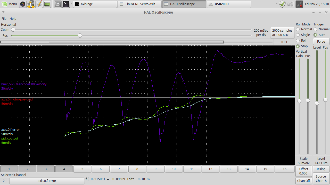
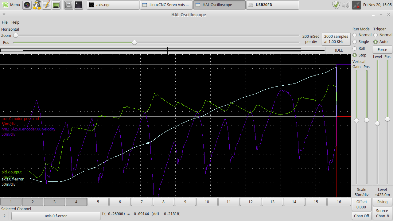
Todd, Many, many thanks!! P= 0.111; I will reset trigger just after sending this reply. You asked about a way to change "jumper of dip switch that changes the feedback direction" this is on the driver I should be investigating?
many thanks!
Edit: Attached are the pic of same settings. P;I, etc (look careful at trace settings!, I had to tweak scale between pics). In the .ini file, the f-errors are still wide open. One of the pics is the beginning of a move, the other is at the end of different move of table, but same settings.
Many thanks!
Last edit: 20 Nov 2020 13:28 by new2linux. Reason: Pic
Please Log in or Create an account to join the conversation.
- new2linux
- Offline
- Platinum Member
-
Less
More
- Posts: 711
- Thank you received: 9
20 Nov 2020 20:18 - 23 Nov 2020 18:22 #189918
by new2linux
Replied by new2linux on topic Replacing Advanced Motion Controls "brush type 12A8 with "Axcent" amplifier
Todd, Many thanks. Attached are a few pics of the tuning with (SW1-6-OFF). This may do what you have asked about, I am not completely shore.
Pic sw1-6off1 is P 0.111; I 0.0; D .01; FF1 .001; FF2 .0001; DEADBAND .000001
Pic sw1-6 is P 0.107; I .01; D .001; FF1 .01; FF2 .001555; DEADBAND .0155
I have asked AMC about your question: Is there a dip switch that changes the feedback direction? SW1-6 goes to off.
this was the response: The fact that the drive is moving the motors in the correct direction for a given command, and that they are not running away means that the encoders are working correctly with the drive.
That makes me wonder if the encoder signal is reversed at the controller side, but I don't know anything about the Linux controller so I don't know how it connects.
Many thanks!
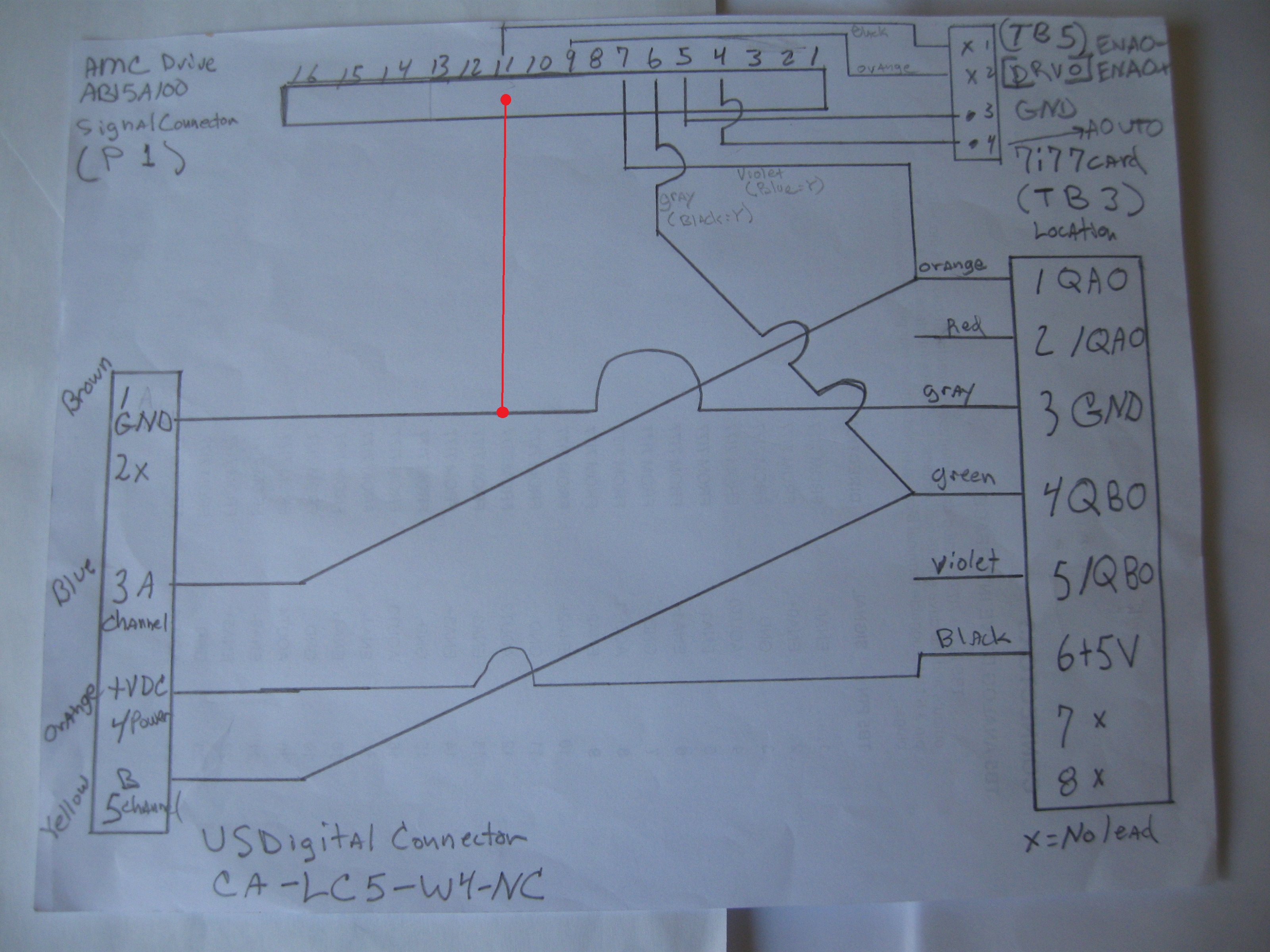
Edit: Referring to the NEW diagram attached, showing GND attached from TB3 (location 3 GND) to the drive pin 11? The diagram is not clear on the AMC (P1) connection, the pins used are pin 4 (+Ref IN); pin 5 (-Ref IN); pin 6 (Encoder B IN); pin 7 (Encoder A IN); pin 9 (INHIBIT/ENABLE); & pin 11 GND.
Edit: The "FERROR & MIN_ERROR" still has wide tolerance.
Pic sw1-6off1 is P 0.111; I 0.0; D .01; FF1 .001; FF2 .0001; DEADBAND .000001
Pic sw1-6 is P 0.107; I .01; D .001; FF1 .01; FF2 .001555; DEADBAND .0155
I have asked AMC about your question: Is there a dip switch that changes the feedback direction? SW1-6 goes to off.
this was the response: The fact that the drive is moving the motors in the correct direction for a given command, and that they are not running away means that the encoders are working correctly with the drive.
That makes me wonder if the encoder signal is reversed at the controller side, but I don't know anything about the Linux controller so I don't know how it connects.
Many thanks!
Edit: Referring to the NEW diagram attached, showing GND attached from TB3 (location 3 GND) to the drive pin 11? The diagram is not clear on the AMC (P1) connection, the pins used are pin 4 (+Ref IN); pin 5 (-Ref IN); pin 6 (Encoder B IN); pin 7 (Encoder A IN); pin 9 (INHIBIT/ENABLE); & pin 11 GND.
Edit: The "FERROR & MIN_ERROR" still has wide tolerance.
Last edit: 23 Nov 2020 18:22 by new2linux. Reason: To add complete wiring diagram, add FERROR & MIN_ERROR comment.Edit; add diagran with GND
Please Log in or Create an account to join the conversation.
- new2linux
- Offline
- Platinum Member
-
Less
More
- Posts: 711
- Thank you received: 9
23 Nov 2020 19:03 - 24 Nov 2020 14:45 #190136
by new2linux
Replied by new2linux on topic Replacing Advanced Motion Controls "brush type 12A8 with "Axcent" amplifier
I have tried the new diagram, now no motion at all. If you try "jog" the velocity in DRO shows correctly the feed rate, but no motion. The yellow "shows the tool movement on DRO screen" does show motion, but table does not move.
Edit: SW1-6 OFF or ON = no effect
Edit: After conversation with AMC the diagram recommended is attached (I worked with this for a while) and after continuity checking for my piece of mind all checked ok, with this 1 question. The shield around the leads going to encoder are grounded to case of encoder on that end, but in the electrical control box (do not connect to 7i77 card), they stop after connecting to GND inside el cabinet. Should they go under screw 3 (GND) on TB3? see attached diagram.
many thanks
Last edit: 24 Nov 2020 14:45 by new2linux. Reason: sw1-6; asked question, and clearified
Please Log in or Create an account to join the conversation.
- Todd Zuercher
-
- Away
- Platinum Member
-
Less
More
- Posts: 4757
- Thank you received: 1459
24 Nov 2020 15:35 #190205
by Todd Zuercher
Replied by Todd Zuercher on topic Replacing Advanced Motion Controls "brush type 12A8 with "Axcent" amplifier
The cable shield should only be connected at one end. (normally to a frame ground or central ground bolt at the control cabinet.) And should not be connected to any of the ground wires or terminals of the control wiring.
The above wiring diagram looks correct to me with the possible exception of there may need to be a ground reference connection between the drive and encoder/7i77.
The above wiring diagram looks correct to me with the possible exception of there may need to be a ground reference connection between the drive and encoder/7i77.
Attachments:
The following user(s) said Thank You: new2linux
Please Log in or Create an account to join the conversation.
- new2linux
- Offline
- Platinum Member
-
Less
More
- Posts: 711
- Thank you received: 9
24 Nov 2020 16:53 #190206
by new2linux
Replied by new2linux on topic Replacing Advanced Motion Controls "brush type 12A8 with "Axcent" amplifier
Todd, Many thanks!! As per your suggestion I have made the changes as to add lead from under screw at TB3 contact 3; to TB5 contact 1. If SW1-6 is OFF; red LED on drives; green blink on 7i77; F1 down or up DRO works; F2 down x motor osculates and y axis motor "runs away".
If SW1-6 is ON; red LED on drives, except green while in "runs away"; green blink on 7i77; F1 down or up DRO works; F2 down "x" motor no motion (does not resist motion, ether) and y axis motor "runs away".
I have contact with AMC what should I be asking? Many thanks!
If SW1-6 is ON; red LED on drives, except green while in "runs away"; green blink on 7i77; F1 down or up DRO works; F2 down "x" motor no motion (does not resist motion, ether) and y axis motor "runs away".
I have contact with AMC what should I be asking? Many thanks!
Please Log in or Create an account to join the conversation.
- Todd Zuercher
-
- Away
- Platinum Member
-
Less
More
- Posts: 4757
- Thank you received: 1459
24 Nov 2020 18:39 - 24 Nov 2020 18:41 #190210
by Todd Zuercher
Replied by Todd Zuercher on topic Replacing Advanced Motion Controls "brush type 12A8 with "Axcent" amplifier
Are you certain of your pin numbering on the drives? I believe that Pin #1 should be the furthest one away from the motor plug.
I don't have any idea why your x is osculating the way it is. (It is almost as if the encoder signal is connected to the Hall inputs of the drive, and why I asked if you might have the plug numbering backwards.)
Believe it or not the Y running away actually may be less mystifying than what is happening with the X. (Although it can be very frightening when it happens.) It means that a feedback signal is wrong, missing or opposite of the command (At least on a system that is mostly connected correctly.) What happens is the control says to move one way but it (or the drive) sees it moving the other way (or not moving at all), so It tells it to go faster or push harder to correct for the wrong (or missing) movement and the motor "runs away" at it's max velocity.
I don't think I can do much more diagnosis of this remotely. I can't think of what to check next. You might be better off having someone who knows what they are doing look at it in person.
Last edit: 24 Nov 2020 18:41 by Todd Zuercher.
The following user(s) said Thank You: new2linux
Please Log in or Create an account to join the conversation.
- new2linux
- Offline
- Platinum Member
-
Less
More
- Posts: 711
- Thank you received: 9
24 Nov 2020 19:58 - 24 Nov 2020 20:06 #190218
by new2linux
Replied by new2linux on topic Replacing Advanced Motion Controls "brush type 12A8 with "Axcent" amplifier
Todd, Many thanks for your continued support, you are a true gentleman, all the way through. The drives are using the full width plug with only the necessary leads, inserted & soldered to leads, so it only goes one way. I am in contact with AMC about the diagram. As per AMC was suggested to leave leads from encoder and drive (those leads stay with each other) and change out the position on the TB3 plug, (as to change the direction of controller in relation to encoder. I think was how it was explained) on 7i77 card. With that change this is how it functions: No motion at all. If you use "jog" to move table, the velocity increases to match the posted feed rate as it is set by the slider, but no motion from motors.
many thanks!
many thanks!
Last edit: 24 Nov 2020 20:06 by new2linux.
Please Log in or Create an account to join the conversation.
- Todd Zuercher
-
- Away
- Platinum Member
-
Less
More
- Posts: 4757
- Thank you received: 1459
24 Nov 2020 20:31 - 24 Nov 2020 20:32 #190221
by Todd Zuercher
Replied by Todd Zuercher on topic Replacing Advanced Motion Controls "brush type 12A8 with "Axcent" amplifier
What leads did you move where on which axis' drive? It is impossible for us to keep track of what you are changing because you never precisely say what you are changing. Just swapping things willy nilly is going to lead to blown up components.
Can you snap a photo of the drive with the leads plugged in, so that we might see what is going where?
(and if possible the same for the 7i77)
Can you snap a photo of the drive with the leads plugged in, so that we might see what is going where?
(and if possible the same for the 7i77)
Last edit: 24 Nov 2020 20:32 by Todd Zuercher.
The following user(s) said Thank You: new2linux
Please Log in or Create an account to join the conversation.
Moderators: piasdom
- Hardware & Machines
- CNC Machines
- Milling Machines
- Replacing Advanced Motion Controls "brush type 12A8 with "Axcent" amplifier
Time to create page: 0.408 seconds