"Origami" CNC Plasma Build - folding 1200 x 600mm cut area
- Joco
-
 Topic Author
- Offline
- Platinum Member
-

Less
More
- Posts: 532
- Thank you received: 327
27 Jun 2021 04:50 - 27 Jun 2021 04:56 #213001
by Joco
Replied by Joco on topic "Origami" CNC Plasma Build - folding 1200 x 600mm cut area
It's Sunday and after much looking, thinking and planning I took the welding plunge on the table frame. The long sections are 1320mm and the ends are 900mm (well really 899mm but close enough). So I welded them out all out then took a 60grit sanding pad and cleaned it all up with this result. And what's more, much to my delight its FLAT and checked square to around 0.5mm from what I can read off the tape measure.
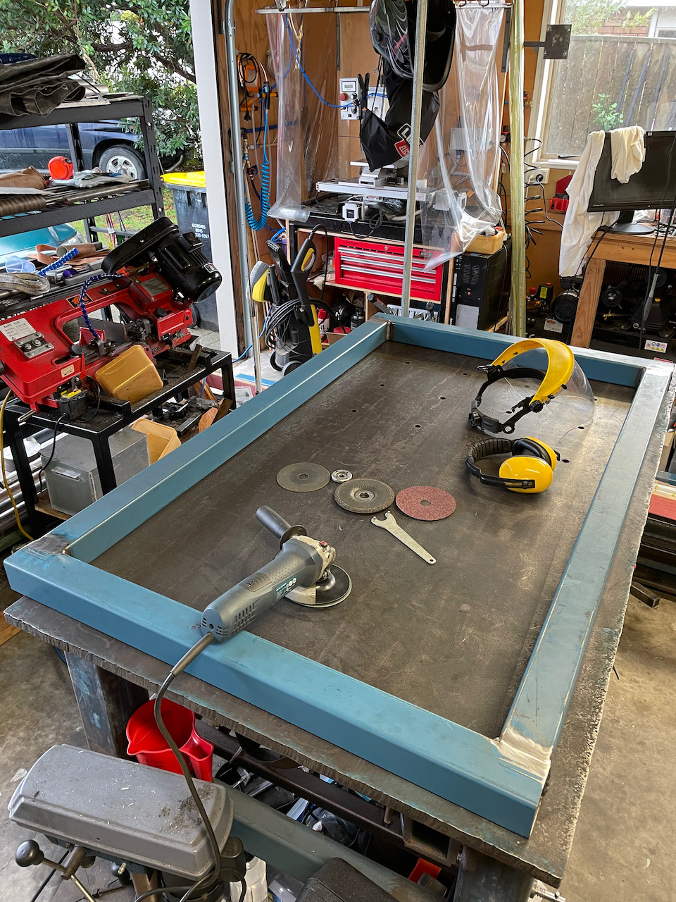
Here is a little video where I test it with the hinge design. I think this could work quite well. Especially as I dial in the centre of gravity.
All in all feeling pretty pleased with the outcome to date.
Cheers - J.
Here is a little video where I test it with the hinge design. I think this could work quite well. Especially as I dial in the centre of gravity.
All in all feeling pretty pleased with the outcome to date.
Cheers - J.
Attachments:
Last edit: 27 Jun 2021 04:56 by Joco.
The following user(s) said Thank You: phillc54, Clive S
Please Log in or Create an account to join the conversation.
- rodw
-

- Offline
- Platinum Member
-
Less
More
- Posts: 11960
- Thank you received: 4074
27 Jun 2021 06:45 #213004
by rodw
Replied by rodw on topic "Origami" CNC Plasma Build - folding 1200 x 600mm cut area
Pretty cool so far!
Please Log in or Create an account to join the conversation.
- Joco
-
Topic Author
- Offline
- Platinum Member
-
Less
More
- Posts: 532
- Thank you received: 327
28 Jun 2021 03:34 #213086
by Joco
Replied by Joco on topic "Origami" CNC Plasma Build - folding 1200 x 600mm cut area
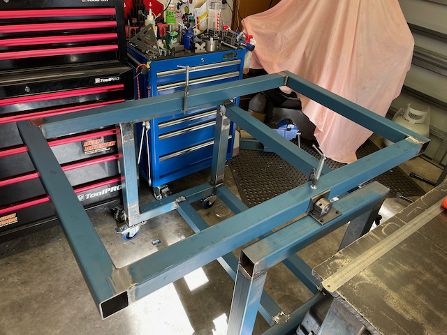
A little bit of tapping and we have a hinged table top in perfect balance with gravity. Been like that for hours, just sitting there.
LOL - what we do when we need a break from work/computer-screen.
LOL - what we do when we need a break from work/computer-screen.
Attachments:
Please Log in or Create an account to join the conversation.
- RNJFAB
- Offline
- Elite Member
-

Less
More
- Posts: 250
- Thank you received: 58
28 Jun 2021 10:09 #213115
by RNJFAB
Replied by RNJFAB on topic "Origami" CNC Plasma Build - folding 1200 x 600mm cut area
Love it Joco.
Super creative solution to suit your needs.
I'm excited to see how this all goes. Not long and you will be making sparks.
Super creative solution to suit your needs.
I'm excited to see how this all goes. Not long and you will be making sparks.
Please Log in or Create an account to join the conversation.
- Joco
-
Topic Author
- Offline
- Platinum Member
-
Less
More
- Posts: 532
- Thank you received: 327
02 Jul 2021 23:13 - 02 Jul 2021 23:14 #213514
by Joco
Replied by Joco on topic "Origami" CNC Plasma Build - folding 1200 x 600mm cut area
A little bit of advice sought: While I realise that plasma is a lot more tolerant on the accuracy front than other machines, just because it is not that a precise process. At least not the version of the process we tend to be building. So, I am pondering the best order of construction: linear rails v's water table.
(a) Do I get the linear rails on and reference their alignment to the top of the flip-table frame then move on to #B or
(b) Do I work on the water table and the slats, get that all created and into a mounting system inside the flip-table frame, looking to get as level/flat as possible then move to #A?
My concern is that once I have the linear rails in I then have to worry about getting the table top wll referenced to their plan. Where as it might easier to do the referencing the other way around.
BUT I plan to have a THCAD so in theory so long as nothing is binding up in motion and variances in the linear motion plane against the water table tops plane would be accomodated by the continual adjustment of the THCAD.
Views on the correct order? Am I over thinking it again? Or some other method/approach I have not considered?
Thanks - James.
Last edit: 02 Jul 2021 23:14 by Joco.
Please Log in or Create an account to join the conversation.
- rodw
-
- Offline
- Platinum Member
-
Less
More
- Posts: 11960
- Thank you received: 4074
03 Jul 2021 00:37 #213526
by rodw
Replied by rodw on topic "Origami" CNC Plasma Build - folding 1200 x 600mm cut area
not much point getting too stressed about it until your slats are in. But in any case, the accuracy is not affected enough to bother with.
eg. If your table was 10mm higher at one end than the other, the dimensional error is about 0.04mm and you can't really expect better than 0.1mm from plasma!
I would just get it moving for now and align it when the slats are in
eg. If your table was 10mm higher at one end than the other, the dimensional error is about 0.04mm and you can't really expect better than 0.1mm from plasma!
I would just get it moving for now and align it when the slats are in
The following user(s) said Thank You: Joco
Please Log in or Create an account to join the conversation.
- Joco
-
Topic Author
- Offline
- Platinum Member
-
Less
More
- Posts: 532
- Thank you received: 327
03 Jul 2021 04:22 #213533
by Joco
Replied by Joco on topic "Origami" CNC Plasma Build - folding 1200 x 600mm cut area
Thanks Rod. So if I am reading you correctly either way is fine so long as take some time to do some alignment against which ever is the fixed reference and to not get too hung up accuracy cose its not (as I noted) that accurate. i.e. if you get 0.1mm on plasma you are doing well.
Cheers.
Cheers.
Please Log in or Create an account to join the conversation.
- RNJFAB
- Offline
- Elite Member
-
Less
More
- Posts: 250
- Thank you received: 58
03 Jul 2021 09:18 #213543
by RNJFAB
Replied by RNJFAB on topic "Origami" CNC Plasma Build - folding 1200 x 600mm cut area
I faced this same issue. So I went with adjustable slat holders meaning I could align to my gantry once it was all together. I think I saw this on someone else build and thought 'that is a sweet way to overcome a problem'.
I made adjustable holders for the slats, that way I'm able to adjust/level all the slats as required (so far this has been twice). I have replaced the slats 3 times now. Each slat has a few lives, right way up, upside down, moved from high cut area to low cut area, ground flat, until they are completely trashed. Slats are 50x3mm steel.
On my table I think I have 5mm difference across 1200mm. However, with the new Mesa 7i96 and thcad10 it's irrelivant as this negats the difference. For perspective last night I cut some alluminium that had been creased for strength, it had a rise and fall of 15mm every 200mm. The thc meant that I could cut this and the torch followed maintaining perfect cut height (honestly it still amazes me).
forum.linuxcnc.org/show-your-stuff/42411...a-cnc?start=0#207451
Pictures 3 & 4 show the adjustable holders.
The following user(s) said Thank You: Joco
Please Log in or Create an account to join the conversation.
- BigJohnT
-

- Offline
- Administrator
-

Less
More
- Posts: 3990
- Thank you received: 994
03 Jul 2021 22:12 #213602
by BigJohnT
Replied by BigJohnT on topic "Origami" CNC Plasma Build - folding 1200 x 600mm cut area
If your going to have a THCAD card and a floating head with a touch off switch then bed level is not important. What is important is the X and Y axes are perpendicular to each other.
I put a slight curve in the sacrificial slats so they would not be fully under a straight cut and that also made the slats very rigid so small plates don't wiggle as the machine moves.
gnipsel.com/images/plasma/
gnipsel.com/shop/plasma/plasma.xhtml
JT
I put a slight curve in the sacrificial slats so they would not be fully under a straight cut and that also made the slats very rigid so small plates don't wiggle as the machine moves.
gnipsel.com/images/plasma/
gnipsel.com/shop/plasma/plasma.xhtml
JT
The following user(s) said Thank You: Joco
Please Log in or Create an account to join the conversation.
- Joco
-
Topic Author
- Offline
- Platinum Member
-
Less
More
- Posts: 532
- Thank you received: 327
04 Jul 2021 02:13 - 04 Jul 2021 02:15 #213635
by Joco
Replied by Joco on topic "Origami" CNC Plasma Build - folding 1200 x 600mm cut area
JT - re the axis being perpendicular to each other I guess other than being careful on construction that next part is getting the racking on the X under control. Dual motors and independent homing with adjustable home reference points being key to that exercise?
After getting distracted by a new SLA 3D printer (never had an SLA one before) I got back to the getting the top frame proper mounted. Success after a little drama trying to drill holes with a hand power drill. Ended up having break out the TIG to fix a bung hole that was off position by just enough to be a problem. Then big mill to the rescue!
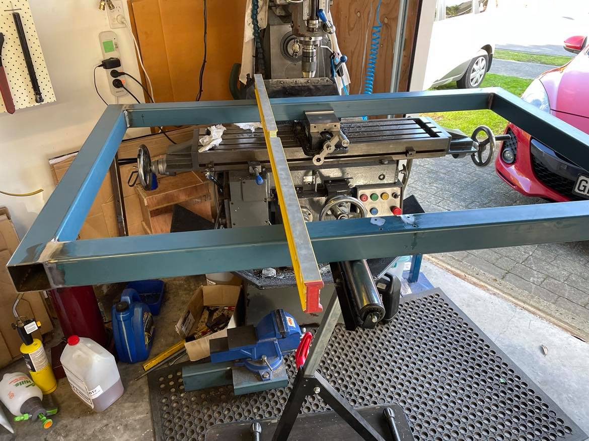
After that it was easy and while it was on there power tapped the holes. We now have finished hinges and top mounted!
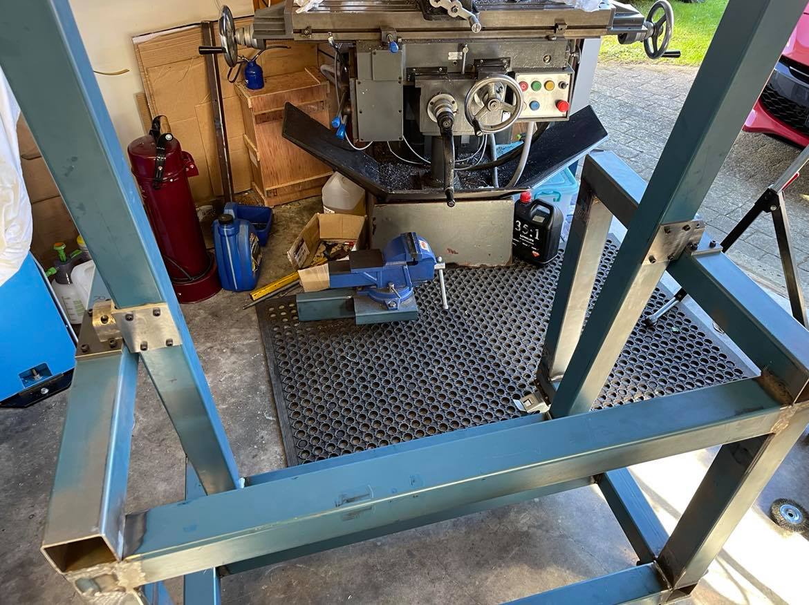
Now there really is no more excuses time to tackle the Y axies linear rails and making the sides to support the X axis. That will allow some motion testing as well. I have the basics of the 7i76e all working on a test bed along with the drivers and motors. I also have all the drive belts and reduction gears for the motors.
Cheers - J.
After getting distracted by a new SLA 3D printer (never had an SLA one before) I got back to the getting the top frame proper mounted. Success after a little drama trying to drill holes with a hand power drill. Ended up having break out the TIG to fix a bung hole that was off position by just enough to be a problem. Then big mill to the rescue!
After that it was easy and while it was on there power tapped the holes. We now have finished hinges and top mounted!
Now there really is no more excuses time to tackle the Y axies linear rails and making the sides to support the X axis. That will allow some motion testing as well. I have the basics of the 7i76e all working on a test bed along with the drivers and motors. I also have all the drive belts and reduction gears for the motors.
Cheers - J.
Attachments:
Last edit: 04 Jul 2021 02:15 by Joco.
The following user(s) said Thank You: tommylight, rodw
Please Log in or Create an account to join the conversation.
Time to create page: 1.040 seconds